
Datasheet


TUSB2046B
TUSB2046BI
SLLS413I –FEBRUARY 2000 –REVISED SEPTEMBER 2013
www.ti.com
TERMINAL FUNCTIONS
TERMINAL
I/O DESCRIPTION
NAME NO.
Power source indicator. BUSPWR is an active-high input that indicates whether the downstream
ports source their power from the USB cable or a local power supply. For the bus-power mode,
BUSPWR 8 I
this terminal must be pulled to 3.3 V, and for the self-powered mode, this terminal must be pulled
low. Input must not change dynamically during operation.
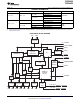
DM0 2 I/O Root port USB differential data minus. DM0 paired with DP0 constitutes the upstream USB port.
11, 15, USB differential data minus. DM1–DM4 paired with DP1–DP4 support up to four downstream USB
DM1–DM4 I/O
19, 23 ports.
DP0 1 I/O Root port USB differential data plus. DP0 paired with DM0 constitutes the upstream USB port.
12, 16, USB differential data plus. DP1–DP4 paired with DM1–DM4 support up to four downstream USB
DP1–DP4 I/O
20, 24 ports.
EEPROM serial clock. When EXTMEM is high, the EEPROM interface is disabled. The EECLK
EECLK 5 O terminal is disabled and must be left floating (unconnected). When EXTMEM is low, EECLK acts
as a 3-state serial clock output to the EEPROM with a 100-μA internal pulldown.
EEPROM serial data/power-management mode indicator. When EXTMEM is high,
EEDATA/GANGED selects between ganged or per-port power overcurrent detection for the
EEDATA/
6 I/O downstream ports. When EXTMEM is low, EEDATA/GANGED acts as a serial data I/O for the
GANGED
EEPROM and is internally pulled down with a 100-μA pulldown. This standard TTL input must not
change dynamically during operation.
When EXTMEM is high, the serial EEPROM interface of the device is disabled. When EXTMEM is
EXTMEM 26 I low, terminals 5 and 6 are configured as the clock and data terminals of the serial EEPROM
interface, respectively.
GND 7, 28 GND terminals must be tied to ground for proper operation.
Overcurrent input. OVRCUR1–OVRCUR4 are active low. For per-port overcurrent detection, one
OVRCUR1 – 10, 14, overcurrent input is available for each of the four downstream ports. In the ganged mode, any
I
OVRCUR4 18, 22 OVRCUR input may be used and all OVRCUR terminals must be tied together. OVRCUR
terminals are active low inputs with noise filtering logic.
Power-on/-off control signals. PWRON1–PWRON4 are active low, push-pull outputs. Push-pull
PWRON1 – 9, 13, outputs eliminate the pullup resistors which open-drain outputs require. However, the external
O
PWRON4 17, 21 power switches that connect to these terminals must be able to operate with 3.3-V inputs because
these outputs cannot drive 5-V signals.
RESET is an active low TTL input with hysteresis and must be asserted at power up. When
RESET is asserted, all logic is initialized. Generally, a reset with a pulse width between 100 μs
RESET 4 I
and 1 ms is recommended after 3.3-V V
CC
reaches its 90%. Clock signal has to be active during
the last 60 μs of the reset window.
Suspend status. SUSPND is an active high output available for external logic power-down
SUSPND 32 O
operations. During the suspend mode, SUSPND is high. SUSPND is low for normal operation.
Test/mode terminal. TSTMODE is used as a test terminal during production testing. This terminal
TSTMODE 31 I
must be tied to ground or 3.3-V V
CC
for normal 6-MHz or 48-MHz operation, respectively.
Test/48-MHz clock input. TSTPLL/48MCLK is used as a test terminal during production testing.
TSTPLL/
27 I/O This terminal must be tied to ground for normal 6-MHz operation. If 48-MHz input clock is desired,
48MCLK
a 48-MHz clock source (no crystal) can be connected to this input terminal.
V
CC
3, 25 3.3-V supply voltage
Crystal 1. XTAL1 is a 6-MHz crystal input with 50% duty cycle. An internal PLL generates the 48-
XTAL1 30 I
MHz and 12-MHz clocks used internally by the ASIC logic.
Crystal 2. XTAL2 is a 6-MHz crystal output. This terminal must be left open when using an
XTAL2 29 O
oscillator.
4 Submit Documentation Feedback Copyright © 2000–2013, Texas Instruments Incorporated
Product Folder Links: TUSB2046B TUSB2046BI