
Datasheet


www.ti.com
TSC2301 AUDIO CONTROL REGISTERS
TSC2301
SLAS371D – SEPTEMBER 2002 – REVISED AUGUST 2004
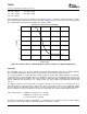
Table 30. Power Consumption by Mode of Operation
Operating Mode Description Register 05h Bit Values Power Consumption
Typ Units
15 14 13 12 11 10 9 8 6 5 4
Stereo Record and Playback
Mono record, line playback, 48 kHz 0 0 1 1 1 0 0 1 1 0 0 45 mW
Mono record, line playback, 8 kHz 0 0 1 1 1 0 0 1 1 0 0 38 mW
Stereo record, line playback, 48 kHz 0 0 1 1 1 0 0 0 1 0 0 60 mW
Stereo record, line playback, 8 kHz 0 0 1 1 1 0 0 0 1 0 0 48 mW
Stereo Playback Only
Line playback only, 48 kHz 0 0 1 1 1 0 1 1 1 0 0 28 mW
Headphone playback only, 48 kHz 0 0 1 0 1 0 1 1 1 0 0 34 mW
Record Only
Stereo line record only, 48 kHz 0 0 1 1 1 1 0 0 1 0 0 34 mW
Stereo line record only, 8 kHz 0 0 1 1 1 1 0 0 1 0 0 26 mW
Mono record, 48 kHz 0 0 1 1 1 1 0 1 1 0 0 19 mW
Mono record only, 8 kHz 0 0 1 1 1 1 0 1 1 0 0 15 mW
Analog Bypass
Line in to line out 0 0 0 1 1 1 1 1 1 0 0 10 mW
Line in to headphone out 0 0 0 0 1 1 1 1 1 0 0 13 mW
Power Down
Power down all 1 1 X X X X X X X 0 0 0.5 µW
Power down, VCM enabled 1 0 X X X X X X X 0 0 0.8 µW
TSC2301 Audio Control Register (Page 2, Address 00H)
The audio control register of the TSC2301 controls the digital audio interface, the microphone preamp gain, the
record multiplexer settings, and the ADC highpass filter pole. This register determines which ADC high pass filter
response is selected, as well as which audio inputs are connected to the stereo ADCs. The gain of the MIC input
(0 to 12 dB) is also selected. This register is also used to tell the data converters the frequency of MCLK, along
with the frequency of LRCLK (ADC and DAC sample rates). The format of the audio data is also selected.
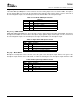
The audio control register is formatted as follows:
Bit 15 Bit 14 Bit 13 Bit 12 Bit 11 Bit 10 Bit 9 Bit 8 Bit 7 Bit 6 Bit 5 Bit 4 Bit 3 Bit 2 Bit 1 Bit 0
MSB LSB
HPF1 HPF0 INML1 INML0 INMR1 INMR0 MICG MICG MCLK MCLK I2SFS I2SFS I2SFS I2SFS I2SFM I2SFM0
1 0 1 0 3 2 1 0 1
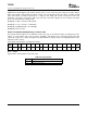
Bits [15:14] — HPF1-HPF0
ADC High Pass Filter. These two bits select the pass-band for the high-pass filter or disable the filter. The default
state of the filter is enabled, with -3-dB frequency at 0.000019xFs.
Table 31. High-Pass Filter Operation
HPF[1:0]
HPF1 HPF0 Description
0 0 HPF Disabled, signal passes through unaltered
0 1 HPF -3-dB frequency = 0.1xFs
1 0 HPF -3-dB frequency = 0.000078xFs
1 1 HPF -3-dB frequency = 0.000019xFs (default)
74