
Datasheet


Data-Mover Port Interface
54
SGLS139B − October 2003 − Revised April 2004TSB12LV32-EP
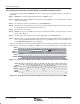
5.1.4.2 Asynchronous Packet Transmit Without Automatic Header Insertion
In this mode, the packet headers and data information are loaded through the data-mover port. This mode
is sometimes called asynchronous packet transmit with manual header insertion. This is because the header
quadlets are not preloaded into the header registers via the microcontroller interface. Instead, they are
inserted manually into the data stream at the same time as the rest of the packet. The following steps further
illustrate the process.
Step 1: Asynchronous header quadlets (three quadlets in quadlet mode and four quadlets in block mode) are
fetched into the header registers through the data-mover port.
Step 2: The header quadlets are then forwarded to the transmitter of the link core.
Step 3: Packet data (payload only) is transmitted through the data mover directly to the transmitter of the link
core.
Step 4: Asynchronous packet is sent to the 1394 bus through the Phy.
CFR REGISTER
Step 4
Header0 Register at 38h
LINK CORE
Transmitter
Receiver
Quadlet#0
Packet Sent to 1394 Bus
Through the Phy
Header1 Register at 3Ch
Quadlet#1
Header2 Register at 40h
Quadlet#2
Header3 Register at 42h
Quadlet#3
Data-
Mover
Port
Step 3 (Packet Data)
Step 2
Step 3
(Packet Data)
Step 1
(Headers Fetched)
Step 1
(Headers Supplied)
Figure 5−12. Asynchronous Transmit Without Auto Header Insertion
5.2 Data-Mover Modes of Operation
The data-mover (DM) port in the GP2Lynx is meant to handle an external memory interface that supplies or
accepts large data packets. The port can be configured to either transmit or receive data packets. The data
can be either asynchronous or isochronous packets. All traffic through the data mover is synchronous to the
rising edge of DMCLK. DMCLK is an output signal at 24.576 MHz.
The data mover operates by setting bits within the DM control register at 04h. The data mover has eight modes
of operation which are specified by the DMASYNC, DMHDR, and DMRX bits in the DM control register at 04h.
Table 5−1 shows all the DM modes of operation.