
Datasheet

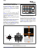


(a) Example DRB (SON) Package Measurement
(b) Example DCQ (SOT-223) Package Measurement
1mm
T on top
of IC
T
T on PCB
surface
B
(c) Example KTT (DDPAK) Package Measurement
1mm
X
X
T
T
T
B
1mm
T on of IC
T
top
(1)
T on PCB
surface
B
(2)
35
30
25
20
15
10
5
0
Y Yand ( C/W)
JT JB
°
0 2
4
6 8 10
Board Copper Area (in )
2
51 3 7 9
DCQ Y
JT
DCQ
DRB
KTT
KTT Y
JT
DRB Y
JT
Y
JB
Y Y
JT J T JT D
:T =T + P·
Y Y
JB J B JB D
:T =T + P·
TPS796
SLVS351O –SEPTEMBER 2002–REVISED NOVEMBER 2013
www.ti.com
ESTIMATING JUNCTION TEMPERATURE
Using the thermal metrics Ψ
JT
and Ψ
JB
, as shown in
the Thermal Information table, the junction
temperature can be estimated with corresponding
formulas (given in Equation 6). For backwards
compatibility, an older θ
JC
,Top parameter is listed as
well.
(6)
Where P
D
is the power dissipation shown by
Equation 5, T
T
is the temperature at the center-top of
the IC package, and T
B
is the PCB temperature
measured 1mm away from the IC package on the
PCB surface (as Figure 26 shows).
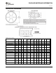
Figure 25. Ψ
JT
and Ψ
JB
vs Board Size
NOTE: Both T
T
and T
B
can be measured on actual
application boards using a thermo-gun (an infrared
For a more detailed discussion of why TI does not
thermometer).
recommend using θ
JC(top)
to determine thermal
characteristics, refer to application report SBVA025,
For more information about measuring T
T
and T
B
, see
Using New Thermal Metrics, available for download
the application note SBVA025, Using New Thermal
at www.ti.com. For further information, refer to
Metrics, available for download at www.ti.com.
application report SPRA953, IC Package Thermal
By looking at Figure 25, the new thermal metrics (Ψ
JT
Metrics, also available on the TI website.
and Ψ
JB
) have very little dependency on board size.
That is, using Ψ
JT
or Ψ
JB
with Equation 6 is a good
way to estimate T
J
by simply measuring T
T
or T
B
,
regardless of the application board size.
(1) T
T
is measured at the center of both the X- and Y-dimensional axes.
(2) T
B
is measured below the package lead on the PCB surface.
Figure 26. Measuring Points for T
T
and T
B
12 Submit Documentation Feedback Copyright © 2002–2013, Texas Instruments Incorporated