
Datasheet


SLVS208I − MAY 1999 − REVISED JANUARY 2004
www.ti.com
16
APPLICATION INFORMATION
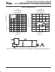
external capacitor requirements (continued)
RESET
OUT
OUT
7
6
5
IN
IN
EN
GND
3
16
14
13
V
I
C1
0.1 µF
RESET
V
O
10 µF
+
TPS767xx
C
o
250 kΩ
Figure 26. Typical Application Circuit (Fixed Versions)
programming the TPS76701 adjustable LDO regulator
The output voltage of the TPS76701 adjustable regulator is programmed using an external resistor divider as shown in
Figure 27. The output voltage is calculated using:
V
O
+ V
ref
ǒ
1 )
R1
R2
Ǔ
(
1)
Where:
ref
= 1.1834 V typ (the internal reference voltage)
Resistors R1 and R2 should be chosen for approximately 50-µA divider current. Lower value resistors can be used but offer
no inherent advantage and waste more power. Higher values should be avoided as leakage currents at FB increase the
output voltage error. The recommended design procedure is to choose R2 = 30.1 kΩ to set the divider current at 50 µA and
then calculate R1 using:
R1 + ǒ
V
O
V
ref
* 1Ǔ R2
(2)
OUTPUT
VOLTAGE
R1 R2
2.5 V
3.3 V
3.6 V
4.75 V
UNIT
33.2
53.6
61.9
90.8
30.1
30.1
30.1
30.1
kΩ
kΩ
kΩ
kΩ
OUTPUT VOLTAGE
PROGRAMMING GUIDE
V
O
V
I
RESET
OUT
FB / NC
R1
R2
GND
EN
IN
≤ 0.9 V
≥ 1.7 V
TPS76701
Reset Output
0.1 µF
250 kΩ
C
o
Figure 27. TPS76701 Adjustable LDO Regulator Programming