
Datasheet


Adjustment by Jumper and Switch
1-3
Introduction
1.3 Adjustment by Jumper and Switch
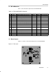
The schematic for the EVM is provided in Figure 1–1.
Table 1–1.TPS75525EVM Jumper Explanations
Jumper or
Switch
Status Description
JP1
Open
(Default)
Pin 3 of JP3 is pulled high to VIN. If pins 2–3 of JP3 are shorted, then U2 EN is pulled
high to V
I
thereby disabling U2. If pins 1–2 of JP3 are shorted, JP1 has no effect.
Short Pin 3 of JP3 is tied low to GND. If pins 2–3 of JP3 are shorted, then U2 EN is tied low to
GND thereby enabling U2. If pins 1–2 of JP3 are shorted, JP1 has no effect.
JP2
Open U1 EN pulled high to V
I
thereby disabling U1.
Short
(Default)
U1 EN tied low to GND thereby enabling U1.
JP3
Short 1-2
(Default)
EN of U2 is tied to pin 1 of JP4. If pins 1–2 of JP4 are shorted, then U1 PG drives U2 EN
for power up sequencing. If pins 2–3 of JP4 are shorted, then changing JP3 has no
effect.
Short 2–3 U2 EN independent of U1. U2 status is controlled by JP1
JP4
Short 1–2
(Default)
PG of U1 is tied to pin 1 of JP3. If pins 1–2 of JP3 are shorted, then U1 PG drives U2 EN
for power up sequencing. If pins 2–3 of JP4 are shorted, then changing JP3 has no
effect.
Short 2–3 U1 can accommodate the TPS75x01 adjustable option regulator using resistors R4
and R5.
Table 1–2.TPS75525EVM Recommended Jumper Settings
JP1 JP2 JP3 JP4 Description
Open Open Short 1–2 Short 1–2
Recommended setup for power up se
q
uencin
g
when JP2 is connected
Open Short Short 1–2 Short 1–2
Recommended
setu
for
ower
u
sequencing
when
JP2
is
connected
to a function generator.
Short Short Short 2–3 Short 1–2 Recommended setup for dc operation.
Short Short Short 2–3 Short 2–3 Recommended setup when replacing U2 with TPS75x01 adjustable
option.