
Datasheet


TPS7301Q, TPS7325Q, TPS7330Q, TPS7333Q, TPS7348Q, TPS7350Q
LOW-DROPOUT VOLTAGE REGULATORS
WITH INTEGRATED DELAYED RESET FUNCTION
SLVS124F – JUNE 1995 – REVISED JANUARY 1999
34
POST OFFICE BOX 655303 • DALLAS, TEXAS 75265
THERMAL INFORMATION
Comparing P
D(total)
with P
D(max)
reveals that the power dissipation in this example does not exceed the maximum
limit. When it does, one of two corrective actions can be taken. The power-dissipation limit can be raised by increasing
either the airflow or the heat-sink area. Alternatively, the internal power dissipation of the regulator can be lowered
by reducing either the input voltage or the load current. In either case, the above calculations should be repeated with
the new system parameters.
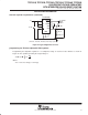
Copper Heat Sink
1 oz Cu
Figure 44. Thermally Enhanced PWB Layout (not to scale) for the 20-Pin TSSOP
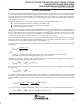
Figure 45
110
90
70
50
0 50 100 150 200 250
130
150
THERMAL RESISTANCE, JUNCTION-TO-AMBIENT
vs
AIR FLOW
170
300
190
C/W
°
JAθ
R – Thermal Resistance, Junction-to-Ambient –
0 cm
2
8 cm
2
2 cm
2
4 cm
2
1 cm
2
Component/Board System
20-Lead TSSOP
Air Flow – ft/min
Figure 46
110
90
70
50
0 50 100 150 200 250
130
150
170
300
190
THERMAL RESISTANCE, JUNCTION-TO-AMBIENT
vs
AIR FLOW
0 cm
2
4 cm
2
2 cm
2
8 cm
2
1 cm
2
C/W
°
JAθ
R – Thermal Resistance, Junction-to-Ambient –
Component/Board System
20-Lead TSSOP
Includes Thermally Conductive
Compound Between Body and Board
Air Flow – ft/min