
Datasheet


TPS6734I
FIXED 12-V 120-mA BOOST-CONVERTER SUPPLY
SLVS127A – AUGUST 1995 – REVISED JANUARY 1999
9
POST OFFICE BOX 655303 • DALLAS, TEXAS 75265
APPLICATION INFORMATION
The TPS6734 operates in a boost circuit as shown in Figures 1 and 11. Figure 1 shows the typical application
circuit, which generates 12 V from a nominal 5-V source. The circuit is ideal for processor interface for energy
management, because EN can be controlled by logic signals to place the 12-V source into the shutdown mode
(3-µA current drain) when 12 V is not needed. An example of such an application is a flash memory device that
requires 12 V for the erase cycle.
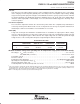
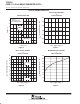
discontinuous mode
The circuit shown in Figure 1 operates in discontinuous mode over most of the range of input voltage and output
current. In discontinuous mode, current through the inductor begins at zero, rises to a peak value, then ramps
down to zero each cycle as shown by the voltage and current waveforms in Figure 8. The ringing in the voltage
waveform on OUT results from a resonance between the inductor and the power switch capacitance and is
normal for discontinuous operation.
0
0246810
5
15
DISCONTINUOUS MODE
20
12 14 16 18
10
1
0.5
0
I – Inductor Current – A
t – Time – µs
V
I
= 5 V
V
O
= 12 V
I
L
= 50 mA
Voltage at Out – V
Figure 8