
Datasheet


0
10
20
30
40
50
60
70
80
90
100
Efficiency-%
0.01 0.1 1
I -OutputCurrent- A
O
0.0010.00010.00001
V =3V
I
V =3.6V
I
V =4.2V
I
V =5V
I
V =2.5V
I
460
465
470
475
480
485
490
495
500
505
0 4000 8000 12000 16000 20000 24000
R -
ISET
W
K - A
ISET
W
T =-40°C
A
T =25°C
A
T =85°C
A
TPS65720
TPS65721
www.ti.com
SLVS979 –OCTOBER 2009
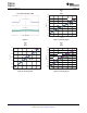
Kset Efficiency vs output current
vs for the complete system;
Riset LDO1 powered by DCDC1 with VDCDC1=2.05V; VLDO1= 1.85V
Figure 21. ICH_SCL[1,0]=11 Figure 22.
DETAILED DESCRIPTION
BATTERY CHARGER AND POWER PATH
The TPS65720 integrates a Li-Ion linear charger and system power path management targeted at space-limited
portable applications. The TPS65720 powers the system while simultaneously and independently charging the
battery. This feature reduces the number of charge and discharge cycles on the battery, allows for proper charge
termination and enables the system to run with a defective or absent battery pack. It also allows instant system
turn-on even with a totally discharged battery. The input power source for charging the battery and running the
system can be an AC adapter or an USB port. The power-path management feature automatically reduces the
charging current if the system load increases. The power-path architecture also permits the battery to
supplement the system current requirements when the adapter cannot deliver the peak system currents.
POWER DOWN
The charger remains in power-down mode when the input voltage at the AC pin is below the under-voltage
lockout threshold (UVLO). During the power-down mode, the host commands through the I
2
C interface are
ignored. The Q1 FET connected between AC and SYS pins is off. The Q2 FET that connects BAT to SYS is ON.
(If <SYSOFF>=1, Q2 is off). During power-down mode, the VOUT(SC2) circuitry is active and monitors for
overload conditions on SYS.
SLEEP MODE
The charger enters sleep mode when V
AC
is greater than UVLO, but below V
BAT
+ V
IN(DT)
. In sleep mode, the
host commands are ignored. The Q1 FET connected between AC and SYS pins is off. The Q2 FET that
connects BAT to SYS is ON. (If <SYSOFF>=1, Q2 is off). During sleep mode, the V
OUT(SC2)
circuitry is active and
monitors for overload conditions on SYS.
STANDBY MODE
When V
AC
is greater than UVLO and VIN is greater than V
BAT
+ V
IN(DT)
, the device is in standby mode.
<CH_PGOOD> =1 to indicate the valid power status and the host commands are read. The device enters
standby mode whenever <AC input current1, AC input current0> = (0,0) or if an input overvoltage condition
occurs. In standby mode, Q1 is OFF and Q2 is ON. (If <SYSOFF>=1, Q2 is off). During standby mode, the
V
OUT(SC2)
circuitry is active and monitors for overload conditions on SYS.
Copyright © 2009, Texas Instruments Incorporated Submit Documentation Feedback 17
Product Folder Link(s): TPS65720 TPS65721