
Datasheet


TPS65217A, TPS65217B, TPS65217C, TPS65217D
SLVSB64F –NOVEMBER 2011–REVISED APRIL 2013
www.ti.com
DESCRIPTION
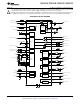
The TPS65217 is a single chip power management IC specifically designed to support the AM335x series of
application processors in portable and 5-V, non-portable applications. It provides a linear battery charger for
single-cell Li-ion and Li-Polymer batteries, dual-input power path, three step-down converters, four LDOs, and a
high-efficiency boost converter to power two strings of up to 10 LEDs each. The system can be supplied by any
combination of USB port, 5-V AC adaptor, or Li-Ion battery. The device is characterized across a -40°C to
+105°C temperature range which makes it suitable for industrial applications. Three high-efficiency 2.25-MHz
step-down converters are targeted at providing the core voltage, memory, and I/O voltage for a processor based
system.
They enter a low power mode at light load for maximum efficiency across the widest possible range of load
currents. For low-noise applications the devices can be forced into fixed frequency PWM using the I
2
C interface.
The step-down converters allow the use of small inductors and capacitors to achieve a small solution size.
LDO1 and LDO2 are intended to support system-standby mode. In SLEEP state output current is limited to
1 mA to reduce quiescent current whereas in normal operation they can support up to 100 mA each. LDO3 and
LDO4 can support up to 200 mA each and can be configured as load switches instead of regulators. All four
LDOs have a wide input voltage range that allows them to be supplied either from one of the DCDC converters
or directly from the system voltage node.
By default only LDO1 is always ON but any rail can be configured to remain up in SLEEP state. Especially the
DCDC converters can remain up in a low-power PFM mode to support processor suspend mode.
The TPS65217 offers flexible power-up and power-down sequencing and several house-keeping functions such
as power-good output, pushbutton monitor, hardware reset function and temperature sensor to protect the
battery.
TPS65217A is targeted at the AM335x processor in the ZCE package which does not support DVFS (dynamic
voltage and frequency scaling). In this package, the VDD_MPU and VDD_CORE supplies are shorted together
and require a single power rail only. DCDC1 output voltage is set to 1.8 V to supply DDR2 memory. TPS65217B
is targeted at the AM335x processor in the ZCZ package which supports DVFS and requires dedicated DCDC
converters for VDD_MPU and VDD_CORE rails. DCDC1 output voltage is set to 1.8V to supply DDR2 memories.
TPS65217C is also targeted at the AM335x processor in the ZCZ package, but DCDC1 output voltage is set to
1.5 V to supply DDR3 memories. LDO3 is set to 1.8 V and supports up to 400-mA of current. Please see
Application note SLVU551 for details.
TPS65217D is identical to TPS65217C with the only difference that DCDC1 output voltage defaults to 1.35 V to
support DDR3L memories.
The TPS65217A, TPS65217B, TPS65217C and TPS65217D come in a 48-pin leadless package (6-mm x 6-mm
QFN) with a 0.4-mm pitch.
2 Submit Documentation Feedback Copyright © 2011–2013, Texas Instruments Incorporated
Product Folder Links: TPS65217A TPS65217B TPS65217C TPS65217D