
Datasheet


PWR_EN
(input)
nWAKEUP
(output)
PB_IN
(input)
USB
(input)
AC
(input)
5s max
50ms
deglitch
50ms
deglitch
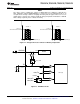
NOTE: If PWR_EN pin is not asserted within
5s of the WAKEUP pin being pulled low,
device will enter OFF or SLEEP mode.
TPS65217A, TPS65217B, TPS65217C, TPS65217D
SLVSB64F –NOVEMBER 2011–REVISED APRIL 2013
www.ti.com
POWER ENABLE PIN (PWR_EN)
The PWR_EN pin is used to keep the unit in ACTIVE mode once it has detected a wakeup event as described in
the Modes of Operation section. If the PWR_EN pin is not asserted within 5 seconds of the nWAKEUP pin being
pulled low, the device will shut down the power and enter either OFF or SLEEP mode, depending on the OFF bit
in the STATUS register. The PWR_EN pin is level sensitive, meaning that it may be pulled high before the
wakeup event.
The PWR_EN pin may also be used to toggle between ACTIVE and SLEEP mode. See SLEEP mode description
for details.
Figure 6. nWAKEUP Timing Diagram. In the example shown the wakeup event is a falling edge on the
PB_IN.
RESET PIN (nRESET)
When the nRESET pin is pulled low, all power rails, including LDO1 and LDO2 are powered down and default
register settings are restored. The device will remain powered down as long as the nRESET pin is held low but
for a minimum of 1 second. Once the nRESET pin is pulled high the device enters ACTIVE mode and the default
power-up sequence will execute. See RESET section for more information.
INTERRUPT PIN (nINT)
The interrupt pin is used to signal any event or fault condition to the host processor. Whenever a fault or event
occurs in the IC the corresponding interrupt bit is set in the INT register, and the open-drain output is pulled low.
The nINT pin is released (returns to HiZ state) and fault bits are cleared when the INT register is read by the
host. However, if a failure persists, the corresponding INT bit remains set and the nINT pin is pulled low again
after a maximum of 32 µs.
Interrupt events include pushbutton pressed/released, USB and AC voltage status change.
The MASK bits in the INT register are used to mask events from generating interrupts. The MASK settings affect
the nINT pin only and have no impact on protection and monitor circuits themselves. Note that persisting event
conditions such as ISINK enabled shutdown can cause the nINT pin to be pulled low for an extended period of
time which can keep the host in a loop trying to resolve the interrupt. If this behavior is not desired, set the
corresponding mask bit after receiving the interrupt and keep polling the INT register to see when the event
condition has disappeared. Then unmask the interrupt bit again.
22 Submit Documentation Feedback Copyright © 2011–2013, Texas Instruments Incorporated
Product Folder Links: TPS65217A TPS65217B TPS65217C TPS65217D