
Datasheet


nINT pin (output)
PB status bit
I2C access to INT register
PB_IN pin (input)
PB is pressed,
INT pin is pulled
low, PB ststusT
bit is set
INT register is read
through I2C while PB
remains pressed. INT
pin is released, PB
stsus bit remains set.
PB is released.
INT pin is pulled
low,PB ststus bit
is reset.
INT register is read
through I2C. INT pin is
released.
PB is pressed,
INT pin is pulled
low, PB stsus bit
is set
PB is released before
INT register is read
through I2C. INT pin
remians low, PB status
bit is reset
INT register is read
through I2C.
PBI interrupt bit
TPS65217A, TPS65217B, TPS65217C, TPS65217D
www.ti.com
SLVSB64F –NOVEMBER 2011–REVISED APRIL 2013
PUSH BUTTON MONITOR (PB_IN)
The TPS65217 has an active-low push-button input which is typically connected to a momentary switch to
ground. The PB_IN input has a 50ms deglitch time and an internal pull-up resistor to an always-on supply. The
push button monitor is used to:
• Power-up the device from OFF or SLEEP mode upon detecting a falling edge on PB_IN.
• Power cycle the device when PB_IN is held low for > 8 s.
Both functions are described in the Modes of Operation section. A change in push-button status (PB_IN
transitions high to low or low to high) is signaled to the host through the PBI interrupt bit in the INT register. The
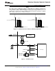
current status of the interrupt can be checked by reading the PB status bit in the STATUS register. A timing
diagram for the push-button monitor is shown in Figure 5.
Figure 5. Timing Diagram of the Push-Button Monitor Circuit
g
nWAKEUP PIN (nWAKEUP)
The nWAKEUP pin is an open drain, active-low output that is used to signal a wakeup event to the system host.
This pin is pulled low whenever the device is in OFF or SLEEP state and detects a wakeup event as described in
the Modes of Operation section. The nWAKEUP pin is delayed 50ms over the power-up event and will remain
low for 50 ms after the PWR_EN pin has been asserted. If the PWR_EN pin is not asserted within 5 seconds of
the power-up event, the device will shut down and enter OFF state. In ACTIVE mode the nWAKEUP pin is
always high. The timing diagram for the nWAKEUP pin is shown in Figure 6.
Copyright © 2011–2013, Texas Instruments Incorporated Submit Documentation Feedback 21
Product Folder Links: TPS65217A TPS65217B TPS65217C TPS65217D