
Datasheet


www.ti.com
Power-Save Mode
32 W
VINDCDC
I =
(PFM_enter)
(1)
24 W
VINDCDC
I =
(PSMDCDC_leave)
(2)
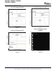
Dynamic Voltage Positioning
FastLoad Transient
PFMMode
LightLoad
PFMMode
Medium/HeavyLoad
COMP_LOW Threshold
PFMMode
LightLoad
-1%
Smooth
IncreasedLoad
PFMMode
Medium/HeavyLoad
+1%
V
OUT_NOM
TPS65050, TPS65051, TPS65052
TPS65054, TPS65056
SLVS710A – JANUARY 2007 – REVISED AUGUST 2007
The Power Save Mode is enabled with the Mode pin set to 0. If the load current decreases, the converters enters
Power Save Mode operation automatically. During Power Save Mode, the converters operate with reduced
switching frequency in PFM mode, and with a minimum quiescent current to maintain high efficiency. The
converter positions the output voltage 1% above the nominal output voltage. This voltage positioning feature
minimizes voltage drops caused by a sudden load step.
To optimize the converter efficiency at light load, the average current is monitored. If in PWM mode, the inductor
current remains below a certain threshold, then Power Save Mode is entered. The typical threshold is calculated
according to Equation 1 :
A. Average output current threshold to enter PFM mode.
A. Average output current threshold to leave PFM mode.
During the Power Save Mode, the output voltage is monitored with a comparator. As the output voltage falls
below the skip comparator threshold (skip comp), the P-channel switch turns on, and the converter effectively
delivers a constant current. If the load is below the delivered current, the output voltage rises until the skip comp
threshold is crossed again, then all switching activity ceases, reducing the quiescent current to a minimum until
the output voltage has dropped below the threshold. If the load current is greater than the delivered current, the
output voltage falls until it crosses the skip comparator low (Skip Comp Low) threshold set to 1% below nominal
V
O
, then Power Save Mode is exited, and the converter returns to PWM mode
These control methods reduce the quiescent current to 12 μ A per converter, and the switching frequency to a
minimum achieving the highest converter efficiency. The PFM mode operates with low output voltage ripple. The
ripple depends on the comparator delay, and the size of the output capacitor; increasing capacitor values
decreases the output ripple voltage.
The Power Save Mode can be disabled by driving the MODE pin high. In forced PWM mode, both converters
operate with fixed frequency PWM mode regardless of the load.
This feature reduces the voltage under/overshoots at load steps from light to heavy load and vice versa. It is
activated in Power Save Mode operation when the converter runs in PFM Mode. It provides more headroom for
both, the voltage drop at a load step and the voltage increase at a load throw-off. This improves load transient
behavior.
At light loads, in which the converter operate in PFM Mode, the output voltage is regulated typically 1% higher
than the nominal value. In the event of a load transient from light load to heavy load, the output voltage drops
until it reaches the skip comparator low threshold set to -1% below the nominal value and enters PWM mode.
During a release from heavy load to light load, the voltage overshoot is also minimized due to active regulation
turning on the N-channel switch.
Figure 19. Dynamic Voltage Positioning
20 Submit Documentation Feedback Copyright © 2007, Texas Instruments Incorporated
Product Folder Link(s): TPS65050, TPS65051, TPS65052 TPS65054, TPS65056