
Datasheet


TPS62150, TPS62150A
TPS62151, TPS62152, TPS62153
SLVSAL5B –NOVEMBER 2011–REVISED JUNE 2013
www.ti.com
These devices have limited built-in ESD protection. The leads should be shorted together or the device placed in conductive foam
during storage or handling to prevent electrostatic damage to the MOS gates.
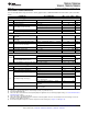
ORDERING INFORMATION
(1)
T
A
OUTPUT VOLTAGE PART NUMBER
(2)
PACKAGE ORDERING PACKAGE MARKING
adjustable TPS62150 TPS62150RGT QUA
adjustable TPS62150A
(3)
TPS62150ARGT PA8I
-40°C to 85°C 1.8 V TPS62151 16-Pin QFN TPS62151RGT QWO
3.3 V TPS62152 TPS62152RGT QWP
5.0 V TPS62153 TPS62153RGT QWQ
(1) For detailed ordering information please check the PACKAGE OPTION ADDENDUM section at the end of this datasheet.
(2) Contact the factory to check availability of other fixed output voltage versions.
(3) While TPS6215X has PG=High Z, TPS62150A features PG=Low, when device is in shutdown through EN, UVLO or Thermal Shutdown.
ABSOLUTE MAXIMUM RATINGS
(1)
over operating free-air temperature range (unless otherwise noted)
MIN MAX UNIT
AVIN, PVIN -0.3 20
V
EN, SS/TR -0.3 V
IN
+0.3
Pin voltage range
(2)
SW -0.3 V
IN
+0.3 V
DEF, FSW, FB, PG, VOS -0.3 7 V
Power Good sink current PG 10 mA
Operating junction temperature range, T
J
-40 125
Temperature range °C
Storage temperature range, T
stg
-65 150
HBM Human body model 2 kV
ESD rating
(3)
CDM Charge device model 0.5 kV
(1) Stresses beyond those listed under absolute maximum ratings may cause permanent damage to the device. These are stress ratings
only, and functional operation of the device at these or any other conditions beyond those indicated under recommended operating
conditions is not implied. Exposure to absolute-maximum-rated conditions for extended periods may affect device reliability.
(2) All voltages are with respect to network ground terminal.
(3) ESD testing is performed according to the respective JESD22 JEDEC standard.
THERMAL INFORMATION
TPS6215X
THERMAL METRIC
(1)
UNITS
RGT 16 PINS
θ
JA
Junction-to-ambient thermal resistance 29.1
θ
JC(TOP)
Junction-to-case(top) thermal resistance 15
θ
JB
Junction-to-board thermal resistance 11
°C/W
ψ
JT
Junction-to-top characterization parameter 0.5
ψ
JB
Junction-to-board characterization parameter 10
θ
JC(BOTTOM)
Junction-to-case(bottom) thermal resistance 3.5
(1) For more information about traditional and new thermal metrics, see the IC Package Thermal Metrics application report, SPRA953.
RECOMMENDED OPERATING CONDITIONS
over operating free-air temperature range (unless otherwise noted)
MIN TYP MAX UNIT
Supply Voltage, V
IN
(at AVIN and P VIN) 3 17 V
Operating free air temperature, T
A
–40 85 °C
Operating junction temperature, T
J
–40 125 °C
2 Submit Documentation Feedback Copyright © 2011–2013, Texas Instruments Incorporated
Product Folder Links: TPS62150, TPS62150A TPS62151 TPS62152 TPS62153