
Datasheet


F
P
+
1
2pR2C1
when R1 u u R2.
F
P
+
ǒ
1
R1
)
1
R2
Ǔ
1
2pC1
F
z
+
1
2pR1 C1
R1 + R2
ǒ
Vout
1.229V
* 1
Ǔ
TPS61080/1
OUT
FB
R1
R2
C 1
R3
100 W
C2
4.7 Fm
TPS61080
TPS61081
www.ti.com
SLVS644D –FEBRUARY 2006–REVISED APRIL 2013
If the calculated duty cycle is less than 5%, minimum load should be considered to the boost output to ensure
regulation. Figure 19 provides quick reference to identify the minimum load requirements for two input voltages.
APPLICATION INFORMATION
PROGRAM OUTPUT VOLTAGE
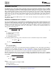
Figure 20. Feed Forward Capacitor Connecting With Feedback Resistor Divider
To program the output voltage, select the values of R1 and R2 (See Figure 20) according to the following
equation.
(4)
A optimum value for R2 is around 50kΩ which sets the current in the resistor divider chain to 1.229V/50kΩ =
24.58μA. The output voltage tolerance depends on the V
FB
accuracy and the resistor divider.
FEED FORWARD CAPACITOR
A feed forward capacitor on the feedback divider, shown in Figure 20, improves transient response and phase
margin. This network creates a low frequency zero and high frequency pole at
(5)
(6)
The frequency of the pole is determined by C1 and paralleled resistance of R1 and R2. For high output voltage,
R1 is much bigger than R2. So
(7)
The loop gains more phase margin from this network when (Fz+Fp)/2 is placed right at crossover frequency,
which is approximately 15kHz with recommended L and C. The typical value for the zero frequency is between
1kHz to 10KHz. For high output voltage, the zero and pole are further apart which makes the feed forward
capacitor very effective. For low output voltage, the benefit of the feed forward capacitor is less visible. Table 2
gives the typical R1, R2 and the feed forward capacitor values at the certain output voltage. However, the
transient response is not greatly improved which implies that the zero frequency is too high or low to increase the
phase margin.
Table 2. Recommended Feed Forward Capacitor
Values With Different Output Voltage
C1(Feed
Output Voltage R1 R2
Forward)
12V 437kΩ 49.9kΩ 33pF
16V 600kΩ 49.9kΩ 42pF
20V 762kΩ 49.9kΩ 56pF
25V 582kΩ 30.1kΩ 120pF
Copyright © 2006–2013, Texas Instruments Incorporated Submit Documentation Feedback 13
Product Folder Links: TPS61080 TPS61081