
Datasheet


SLVS324A − JULY 2001 REVISED NOVEMBER 2004
13
WWW.TI.COM
APPLICATION INFORMATION
voltage inverter
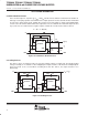
The most common application for these devices is a charge-pump voltage inverter (see Figure 23). This
application requires only two external components; capacitors C
(fly)
and C
O
, plus a bypass capacitor, if
necessary. Refer to the capacitor selection section for suggested capacitor types.
TPS60400
C1− C1+
35
OUTIN
GND
1
2
4
C
I
1 µF
C
O
1 µF
−5 V,
Max 60 mA
Input 5 V
C
(fly)
1 µF
Figure 23. Typical Operating Circuit
For the maximum output current and best performance, three ceramic capacitors of 1 µF (TPS60400,
TPS60403) are recommended. For lower currents or higher allowed output voltage ripple, other capacitors can
also be used. It is recommended that the output capacitors has a minimum value of 1 µF. With flying capacitors
lower than 1 µF, the maximum output power will decrease.