
Datasheet


www.ti.com
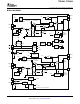
Feedback Loop and Inductor-Capacitor (L-C) Filter Selection
TPS5438x
FB
C
COMP
11.5kW
+
Error Amplifier
0.8V
REF
BOOT
SW
+
R
COMP
Offset
f(I
DRAIN
)
PWMto
Switch
I
SLOPE
I
COMP
TPS54383
TPS54386
R
COMP
(kW)
C
COMP
(pF)
700
700
40
20
UDG-07012
I
COMP
-I
SLOPE
x2
TPS54383 , , TPS54386
SLUS774B – AUGUST 2007 – REVISED OCTOBER 2007
In the feedback signal path, the output voltage setting divider is followed by an internal g
M
-type error amplifier
with a typical transconductance of 30 µ S. An internal series connected R-C circuit from the g
M
amplifier output to
ground serves as the compensation network for the converter. The signal from the error amplifier output is then
buffered and combined with a slope compensation signal before it is mirrored to be referenced to the SW node.
Here, it is compared with the current feedback signal to create a pulse-width-modulated (PWM) signal-fed to
drive the upper MOSFET switch. A simplified equivalent circuit of the signal control path is depicted in Figure 22 .
NOTE:
Noise coupling from the SWx node to internal circuitry of BOOTx may impact narrow
pulse width operation, especially at load currents less than 1 A. See SW Node
Ringing for further information on reducing noise on the SWx node.
Figure 22. Feedback Loop Equivalent Circuit
A more conventional small signal equivalent block diagram is shown in Figure 23 . Here, the full closed loop
signal path is shown. Because the TPS5438x contains internal slope compensation and loop compensation
components, the external L-C filter must be selected appropriately so that the resulting control loop meets criteria
for stability. This approach differs from an externally-compensated controller, where the L-C filter is generally
selected first, and the compensation network is found afterwards. To find the appropriate L and C filter
combination, the Output-to-Vc signal path plots (see the next section ) of gain and phase are used along with
other design criterial to aid in finding the combinations that best results in a stable feedback loop.
Copyright © 2007, Texas Instruments Incorporated Submit Documentation Feedback 17
Product Folder Link(s): TPS54383 TPS54386