
Datasheet


SLVS456C − OCTOBER 2003 − REVISED OCTOBER 2004
www.ti.com
15
1
VIN
VIN
UVLO
PWRGD
RT
SYNC
ENA
COMP
PWRPAD
17
VSENSE
AGND
PGND
VBIAS
LSG
PH
PH
BOOT
2
3
4
5
6
7
8
16
15
14
13
12
11
10
9
U1
TPS54350PWP
C9
10
µF
C3
0.1 µF
1
C4
4
8
Q1
R4
4.7
Ω
C11
3300 pF
1
L1
10 µH
+
C2
100 µF
C6
82 nF
R3
768
Ω
C7
1800 pF
R2
374
Ω
R5
137
Ω
R1
1 k
Ω
C8
33 nF
6 V − 18 V
VOUT 3.3 V @ 3 A
Q1: Fairchild Semiconductor FDR6674A
L1: Vishay IHLP-5050CE
C2: Sanyo 6TPC100M
2367
2
5
1 µF
C1
47
µF
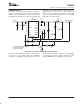
Figure 24. Application Circuit, 12 V to 3.3 V
Figure 24 shows the schematic for a typical TPS54350
application. The TPS54350 can provide up to 3-A output
current at a nominal output voltage of 3.3 V. For proper
thermal performance, the exposed PowerPAD underneath
the device must be soldered down to the printed circuit
board.
DESIGN PROCEDURE
The following design procedure can be used to select
component values for the TPS54350. Alternately, the
SWIFT Designer Software may be used to generate a
complete design. The SWIFT Designer Software uses an
iterative design procedure and accesses a comprehensive
database of components when generating a design. This
section presents a simplified discussion of the design
process.
DESIGN PROCEDURE
To begin the design process a few parameters must be
decided upon. The designer needs to know the following:
D Input voltage range
D Output voltage
D Input ripple voltage
D Output ripple voltage
D Output current rating
D Operating frequency
For this design example, use the following as the input
parameters:
DESIGN PARAMETER EXAMPLE VALUE
Input voltage range 6 V to 18 V
Output voltage 3.3 V
Input ripple voltage 300 mV
Output ripple voltage 30 mV
Output current rating 3 A
Operating frequency 500 kHz
NOTE:
As an additional constraint, the design is set up to be small size
and low component height.
SWITCHING FREQUENCY
The switching frequency is set using the RT pin.
Grounding the RT pin sets the PWM switching frequency
to a default frequency of 250 kHz. Floating the RT pin sets
the PWM switching frequency to 500 kHz. By connecting
a resistor from RT to AGND, any frequency in the range of
250 to 700 kHz can be set. Use equation 8 to determine the
proper value of RT.
RT(kW) +
46000
ƒ
s
(kHz) * 35.9
In this example circuit, RT is not connected and the
switching frequency is set at 500 kHz.
INPUT CAPACITORS
The TPS54350 requires an input decoupling capacitor
and, depending on the application, a bulk input capacitor.
The minimum value for the decoupling capacitor, C9, is
(9)