
Datasheet


SLVS612 − APRIL 2006
12
www.ti.com
APPLICATION INFORMATION
The current limit programming resistor (R
ILIM
) is calculated using equation (13). Care must be taken in choosing
the values used for V
OS
and I
SINK
in the equation. In order to ensure the output current at the overcurrent level,
the minimum value of I
SINK
and the maximum value of V
OS
must be used.
R
ILIM
+
I
OC
R
DS(on)[max]
I
SINK
)
V
OS
I
SINK
(W)
where:
D I
SINK
is the current into the ILIM pin and is 8.6 µA, minimum
D I
OC
is the overcurrent setpoint which is the DC output current plus one-half of the peak inductor current
D V
OS
is the overcurrent comparator offset and is 30 mV, maximum
UDG−02136
HDRV
CLOCK
V
VIN
−V
SW
SS
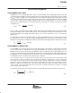
7 CURRENT LIMIT TRIPS
(HDRV CYCLE TERMINATED BY CURRENT LIMIT
TRIP)
7 SOFT-START CYCLES
V
ILIM
t
BLANKING
Figure 4. Typical Current Limit Protection Waveforms
SYNCHRONIZING TO AN EXTERNAL SUPPLY
The TPS40056 can be synchronized to an external clock through the SYNC pin. Synchronization occurs on the
falling edge of the SYNC signal. The synchronization frequency should be in the range of 20% to 30% higher
than its programmed free-run frequency. The clock frequency at the SYNC pin replaces the master clock
generated by the oscillator circuit. Pulling the SYNC pin low programs the TPS40056 to freely run at the
frequency programmed by R
T
.
(13)