
Datasheet


SLVS132F − NOVEMBER 1995 − REVISED OCTOBER 2004
8
www.ti.com
PARAMETER MEASUREMENT INFORMATION
0−10 V dc
xOUT
0.1 µF 4.7 µF
10 V
Current
Loop
1
2
3
4
8
7
6
5
TPS2811
Regulator
+
V
CC
Figure 2. Shoot-through Current Test Setup
50%
90%
1IN
1OUT
50% 50%
90%
10%
50%
10%
t
PLH
t
r
t
f
t
PHL
0 V
0 V
Figure 3. Typical Timing Diagram (TPS2811)
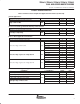
TYPICAL CHARACTERISTICS
Tables of Characteristics Graphs and Application Information
typical characteristics
PARAMETER vs PARAMETER 2 FIGURE PAGE
Rise time Supply voltage 4 10
Fall time Supply voltage 5 10
Propagation delay time Supply voltage 6, 7 10
Supply voltage 8 11
Supply current Load capacitance 9 11
Supply current
Ambient temperature 10 11
Input threshold voltage Supply voltage 11 11
Regulator output voltage Regulator input voltage 12, 13 12
Regulator quiescent current Regulator input voltage 14 12
Peak source current Supply voltage 15 12
Peak sink current Supply voltage 16 13
Shoot-through current
Input voltage, high-to-low 17 13
Shoot-through current
Input voltage, low-to-high 18 13