
Datasheet


R
(ILIM)
− Current-Limiting Resistance − kΩ
0
200
400
600
800
1000
1200
1400
1600
1800
20 30 40 50 60 70 80 90 100
I
(LIMIT)
− USB Current Limit − mA
G009
I
OS(min)
I
(AUX)
= 0 A
V
IN
= 3.3 V
I
OS(max)
I
OS(typ)
I
(AUX)
− Auxiliary Current − mA
1250
1275
1300
1325
1350
1375
1400
1425
1450
0 100 200 300 400 500
I
(LIMIT)
− USB Current Limit − mA
G010
V
IN
= 3.3 V
V
IN
= 4.75 V
V
IN
= 5.2 V
R
L
= 20 kΩ
T
J
= 25°C
I
(AUX)
− Auxiliary Current − mA
625
650
675
700
725
750
775
0 100 200 300 400 500
I
(LIMIT)
− USB Current Limit − mA
G011
R
L
= 40 kΩ
T
J
= 25°C
V
IN
= 4.75 V
V
IN
= 2.4 V
V
IN
= 3.3 V
V
IN
= 5.2 V
TPS2500, TPS2501
www.ti.com
SLVS886C –OCTOBER 2008–REVISED AUGUST 2010
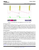
Figure 13. USB Current-Limit Threshold vs R
ILIM
Over Temperature and Process, V
IN
= 3.3 V, I
AUX
= 0 A
In addition to current-limit shifts due to process and temperature, the operating conditions of the boost converter
also affect the current-limit threshold of the USB switch. Figure 13 accounts for process and temperature shifts at
V
IN
= 3.3 V and I
AUX
= 0 A. The following figures show current-limit shift trends over V
IN
and I
AUX
(where I
AUX
is
the auxiliary 5-V load current provided to any non-USB loads). These curves can be used to calculate the USB
current-limit threshold shift for a given application where the input voltage V
IN
range and auxiliary current I
AUX
vary.
Figure 14. USB Current-Limit Threshold vs I
AUX,
Figure 15. USB Current-Limit Threshold vs I
AUX,
R
ILIM
= 20 kΩ, T
A
= 25 °C R
ILIM
= 40 kΩ, T
A
= 25 °C
Copyright © 2008–2010, Texas Instruments Incorporated Submit Documentation Feedback 17
Product Folder Link(s): TPS2500 TPS2501