
Datasheet


TPS2500, TPS2501
SLVS886C –OCTOBER 2008–REVISED AUGUST 2010
www.ti.com
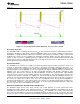
Figure 20. Efficiency vs AUX Current
IN Capacitance
Connect the input capacitance from IN to the reference ground plane. (See the Layout Recommendations
section for connecting PGND and GND to the ground plane.) Input capacitance reduces the ac voltage ripple on
the input rail by providing a low-impedance path for the switching current of the boost converter. The TPS2500
does not have a minimum or maximum input capacitance requirement for operation, but a 10-mF, X7R or X5R
ceramic capacitor is recommended for most applications for reasonable input-voltage ripple performance. There
are several scenarios where it is recommended to use additional input capacitance:
• The output impedance of the upstream power supply is high, or the power supply is located far from the
TPS2500.
• The TPS2500 is tested in a lab environment with long, inductive cables connected to the input, and transient
voltage spikes could exceed the absolute maximum voltage rating of the device.
• The device is operating in Eco-mode control scheme near V
IN
= 1.8 V, where insufficient input capacitance
may cause the input ripple voltage to fall below the minimum 1.75-V (typical) UVLO circuit, causing device
turnoff.
Additionally, it is good engineering practice to use an additional 0.1-mF ceramic decoupling capacitor close to the
IC to prevent unwanted high-frequency noise from coupling into the device.
AUX Capacitance
Connect the boost-converter output capacitance from AUX to the reference ground plane. The AUX capacitance
controls the ripple voltage on the AUX rail and provides a low-impedance path for the switching and
transient-load currents of the boost converter. It also sets the location of the output pole in the control loop of the
boost converter. There are limitations to the minimum and maximum capacitance on AUX. The recommended
minimum capacitance on AUX is a 22-mF, X5R or X7R ceramic capacitor. A 10-V rated ceramic capacitor is
recommended to minimize the capacitance derating loss due to dc bias applied to the capacitor. The low ESR of
the ceramic capacitor minimizes ripple voltage and power dissipation from the large, pulsating currents of the
boost converter and provides adequate phase margin across all recommended operating conditions.
In some applications, it is desirable to add additional AUX capacitance. Additional AUX capacitance reduces
transient undershoot/overshoot voltages due to load steps and reduces AUX ripple in the Eco-mode control
scheme. Adding AUX capacitance changes the control loop, resulting in reduced phase margin, so it is
recommended that no more than 220 mF of additional capacitance be added in parallel to the 22-mF ceramic
capacitor. The combined output capacitance on AUX and USB should not exceed 500 mF.
20 Submit Documentation Feedback Copyright © 2008–2010, Texas Instruments Incorporated
Product Folder Link(s): TPS2500 TPS2501