
Datasheet


TPS23757
www.ti.com
SLVS948D –JULY 2009–REVISED NOVEMBER 2013
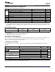
RECOMMENDED OPERATING CONDITIONS
(1)
Voltage with respect to V
SS
(unless otherwise noted)
MIN NOM MAX UNIT
Input voltage range ARTN, COM, PPD, RTN, V
DD
, V
DD1
0 57 V
Input voltage range APb, V
C
to [ARTN, COM] 0 18 V
V
I
Input voltage range APD, CTL to [ARTN, COM] 0 V
B
V
Input voltage range CS to [ARTN, COM] 0 2 V
I Continuous RTN current (T
J
≤ 125°C)
(2)
400 mA
I
S
Sourcing current, V
B
0 2.5 5 mA
C V
B
capacitance 0.08 μF
R
BLNK
0 350 kΩ
Synchronization pulse width input (when used) 25 ns
T
J
Operating junction temperature range –40 125 °C
(1) ARTN and COM tied to RTN.
(2) This is the minimum current-limit value. PDs should be designed for maximum currents below this value to provide for unit power-draw
tolerance. IEEE 802.3at type 1 and IEEE 802.3-2008 compliant devices should not draw average current greater than 350 mA, or their
class power.
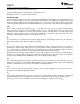
DISSIPATION RATINGS
Ψ
JT
θ
JA
θ
JA
PACKAGE
°C/W
(1)
°C/W
(2)
°C/W
(3)
PWP (TSSOP-20) 0.7 / 0.45 135 74
(1) Thermal resistance junction to case top, low-k / high-k board, natural convection, T
J
= T
TOP
+ (Ψ
JT
x P
J
). Use Ψ
JT
to validate T
J
from
measurements.
(2) JEDEC method with low-k board (1 signal layer), natural convection.
(3) JEDEC method with high-k board (2 signal – 2 plane layers).
ELECTRICAL CHARACTERISTICS
Unless otherwise noted: CS=COM=APD=CTL=RTN=ARTN, GATE and GAT2 float, R
FRS
= 68.1 kΩ, R
BLNK
= 249 kΩ, DT = V
B
,
PPD = V
SS
, APb open, C
VB
= C
VC
= 0.1 μF, R
DEN
= 24.9 kΩ, R
CLS
open, 0 V ≤ (V
DD
, V
DD1
) ≤ 57 V, 0 V ≤ V
C
≤ 18 V,
–40°C ≤ T
J
≤ 125°C. Typical specifications are at 25°C.
CONTROLLER SECTION ONLY
[V
SS
= RTN and V
DD
= V
DD1
] or [V
SS
= RTN = V
DD
], all voltages referred to [ARTN, COM] (unless otherwise
noted).
PARAMETER TEST CONDITIONS MIN TYP MAX UNIT
V
C
V
CUV
V
C
rising 8.7 9 9.3
UVLO V
V
CUVH
Hysteresis
(1)
3.3 3.5 3.7
Operating current V
C
= 12 V, CTL = V
B
, R
DT
= 68.1 kΩ 0.7 0.92 1.2 mA
V
DD1
= 10.2 V, V
C
(0) = 0 V 50 85 175
Bootstrap startup time,
t
ST
ms
C
VC
= 22 μF
V
DD1
= 35 V, V
C
(0) = 0 V 27 45 92
V
DD1
= 10.2 V, V
C
= 8.6 V 0.44 1.06 1.80
Startup current source - I
VC
mA
V
DD1
= 48 V, V
C
= 0 V 2.7 4.8 6.8
V
B
Voltage 6.5 V ≤ V
C
≤ 18 V, 0 ≤ I
VB
≤ 5 mA 4.8 5.10 5.25 V
(1) The hysteresis tolerance tracks the rising threshold for a given device.
Copyright © 2009–2013, Texas Instruments Incorporated Submit Documentation Feedback 3