
Datasheet


P
O
− Output Power − W
0
10
20
30
40
50
60
70
80
90
100
0 5 10 15 20 25 30
η − Efficiency − %
G013
Gain = 20 dB
Z
L
= 4 Ω + 33 µH
V
CC
= 24 V
V
CC
= 12 V
P
O(Tot)
− Total Output Power − W
0.0
0.2
0.4
0.6
0.8
1.0
1.2
0 5 10 15 20 25 30
I
CC
− Supply Current − A
G014
V
CC
= 12 V
V
CC
= 24 V
Gain = 20 dB
Z
L
= 8 Ω + 66 µH
P
O
− Output Power − W
0
10
20
30
40
50
60
70
80
90
100
0 5 10 15 20 25 30
η − Efficiency − %
G012
V
CC
= 24 V
Gain = 20 dB
Z
L
= 8 Ω + 66 µH
V
CC
= 12 V
f − Frequency − Hz
Phase − °
100
50
0
−300
0
5
10
15
20
25
30
35
40
Gain − dB
−50
−100
−150
10 100 10k 100k1k
G009
Phase
Gain
−200
−250
C
I
= 1 µF
Gain = 20 dB
Filter = Audio Precision AUX-0025
V
CC
= 12 V
V
I
= 0.1 Vrms
Z
L
= 8 Ω + 66 µH
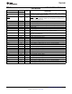
TPA3112D1
www.ti.com
SLOS654C –SEPTEMBER 2009–REVISED JULY 2012
TYPICAL CHARACTERISTICS (continued)
(All Measurements taken at 1 kHz, unless otherwise noted. Measurements were made using the TPA3112D2 EVM which is
available at ti.com.)
GAIN/PHASE EFFICIENCY
vs vs
FREQUENCY OUTPUT POWER
Note: Dashed line represents thermally limited region.
Figure 10. Figure 11.
EFFICIENCY SUPPLY CURRENT
vs vs
OUTPUT POWER TOTAL OUTPUT POWER
Note: Dashed line represents thermally limited region. Note: Dashed line represents thermally limited region.
Figure 12. Figure 13.
Copyright © 2009–2012, Texas Instruments Incorporated Submit Documentation Feedback 9
Product Folder Link(s): TPA3112D1