
Datasheet


TPA3112D1
SLOS654C –SEPTEMBER 2009–REVISED JULY 2012
www.ti.com
One important aspect of the ferrite bead selection is the type of material used in the ferrite bead. Not all ferrite
material is alike, so it is important to select a material that is effective in the 10 to 100 MHz range which is key to
the operation of the Class D amplifier. Many of the specifications regulating consumer electronics have
emissions limits as low as 30 MHz. It is important to use the ferrite bead filter to block radiation in the 30 MHz
and above range from appearing on the speaker wires and the power supply lines which are good antennas for
these signals. The impedance of the ferrite bead can be used along with a small capacitor with a value in the
range of 1000 pF to reduce the frequency spectrum of the signal to an acceptable level. For best performance,
the resonant frequency of the ferrite bead/ capacitor filter should be less than 10 MHz.
Also, it is important that the ferrite bead is large enough to maintain its impedance at the peak currents expected
for the amplifier. Some ferrite bead manufacturers specify the bead impedance at a variety of current levels. In
this case it is possible to make sure the ferrite bead maintains an adequate amount of impedance at the peak
current the amplifier will see. If these specifications are not available, it is also possible to estimate the bead
current handling capability by measuring the resonant frequency of the filter output at very low power and at
maximum power. A change of resonant frequency of less than fifty percent under this condition is desirable.
Examples of ferrite beads which have been tested and work well with the TPA3112D2 include 28L0138-80R-10
and HI1812V101R-10 from Steward and the 742792510 from Wurth Electronics.
A high quality ceramic capacitor is also needed for the ferrite bead filter. A low ESR capacitor with good
temperature and voltage characteristics will work best.
Additional EMC improvements may be obtained by adding snubber networks from each of the class D outputs to
ground. Suggested values for a simple RC series snubber network would be 10 ohms in series with a 330 pF
capacitor although design of the snubber network is specific to every application and must be designed taking
into account the parasitic reactance of the printed circuit board as well as the audio amp. Take care to evaluate
the stress on the component in the snubber network especially if the amp is running at high PVCC. Also, make
sure the layout of the snubber network is tight and returns directly to the PGND or the PowerPad™ beneath the
chip.
Efficiency: LC Filter Required With the Traditional Class-D Modulation Scheme
The main reason that the traditional class-D amplifier needs an output filter is that the switching waveform results
in maximum current flow. This causes more loss in the load, which causes lower efficiency. The ripple current is
large for the traditional modulation scheme, because the ripple current is proportional to voltage multiplied by the
time at that voltage. The differential voltage swing is 2 x V
CC
, and the time at each voltage is half the period for
the traditional modulation scheme. An ideal LC filter is needed to store the ripple current from each half cycle for
the next half cycle, while any resistance causes power dissipation. The speaker is both resistive and reactive,
whereas an LC filter is almost purely reactive.
The TPA3112D1 modulation scheme has little loss in the load without a filter because the pulses are short and
the change in voltage is V
CC
instead of 2 x V
CC
. As the output power increases, the pulses widen, making the
ripple current larger. Ripple current could be filtered with an LC filter for increased efficiency, but for most
applications the filter is not needed.
An LC filter with a cutoff frequency less than the class-D switching frequency allows the switching current to flow
through the filter instead of the load. The filter has less resistance but higher impedance at the switching
frequency than the speaker, which results in less power dissipation, therefore increasing efficiency.
When to Use an Output Filter for EMI Suppression
The TPA3112D1 has been tested with a simple ferrite bead filter for a variety of applications including long
speaker wires up to 125 cm and high power. The TPA3112D1 EVM passes FCC Class B specifications under
these conditions using twisted speaker wires. The size and type of ferrite bead can be selected to meet
application requirements. Also, the filter capacitor can be increased if necessary with some impact on efficiency.
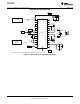
There may be a few circuit instances where it is necessary to add a complete LC reconstruction filter. These
circumstances might occur if there are circuits near which are sensitive to noise. Therefore, a classic second
order Butterworth filter similar to those shown in Figure 19 through Figure 21 can be used.
16 Submit Documentation Feedback Copyright © 2009–2012, Texas Instruments Incorporated
Product Folder Link(s): TPA3112D1