
User's Manual Stereo Amplifier TPA3008D2


Table Of Contents
- FEATURES
- DESCRIPTION
- APPLICATIONS
- ABSOLUTE MAXIMUM RATINGS
- DISSIPATION RATING TABLE
- RECOMMENDED OPERATING CONDITIONS
- AVAILABLE OPTIONS
- DC ELECTRICAL CHARACTERISTICS
- AC ELECTRICAL CHARACTERISTICS
- TYPICAL CHARACTERISTICS
- APPLICATION INFORMATION
- CLASS-D OPERATION
- Traditional Class-D Modulation Scheme
- TPA3008D2 Modulation Scheme
- Efficiency: LC Filter Required With the Traditional Class-D Modulation Scheme
- Effects of Applying a Square Wave Into a Speaker
- When to Use an Output Filter for EMI Suppression
- Gain setting via GAIN0 and GAIN1 inputs
- INPUT RESISTANCE
- INPUT CAPACITOR, CI
- SHUTDOWN OPERATION
- USING LOW-ESR CAPACITORS
- SHORT-CIRCUIT PROTECTION AND AUTOMATIC RECOVERY FEATURE
- THERMAL PROTECTION
- PRINTED-CIRCUIT BOARD (PCB) LAYOUT
- BASIC MEASUREMENT SYSTEM
- DIFFERENTIAL INPUT AND BTL OUTPUT
- CLASS-D RC LOW-PASS FILTER
www.ti.com
TPA3008D2
SLOS435A – MAY 2004 – REVISED JULY 2004
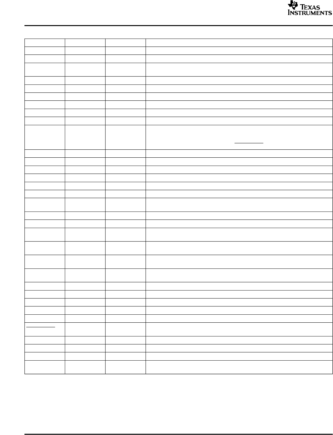
TERMINAL FUNCTIONS
PIN NAME PIN NUMBER I/O DESCRIPTION
AGND 26, 30 - Analog ground for digital/analog cells in core
AV
CC
33 - High-voltage analog power supply, not connected internally to PVCCR or PVCCL
5-V Regulated output for use by internal cells and GAIN0, GAIN1 pins only. Not
AV
DD
29 O
specified for driving other external circuitry.
AV
DD
REF 7 O 5-V Reference output—connect to gain setting resistor or directly to GAIN0, GAIN1.
BSLN 13 - Bootstrap I/O for left channel, negative high-side FET
BSLP 24 - Bootstrap I/O for left channel, positive high-side FET
BSRN 48 - Bootstrap I/O for right channel, negative high-side FET
BSRP 37 - Bootstrap I/O for right channel, positive high-side FET
COSC 28 I/O I/O for charge/discharging currents onto capacitor for ramp generator.
Short-circuit detect fault output.
FAULT = high, short-circuit detected.
FAULT 11 O
FAULT = low, normal operation.
Status is reset when power is cycled or SHUTDOWN is cycled.
GAIN0 9 I Gain select least significant bit. TTL logic levels with compliance to AV
DD
.
GAIN1 10 I Gain select most significant bit. TTL logic levels with compliance to AV
DD
.
LINN 6 I Negative audio input for left channel
LINP 5 I Positive audio input for left channel
LOUTN 16, 17 O Class-D 1/2-H-bridge negative output for left channel
LOUTP 20, 21 O Class-D 1/2-H-bridge positive output for left channel
8, 12, 31, 32,
NC - No internal connection
34, 35
PGNDL 18, 19 - Power ground for left channel H-bridge
PGNDR 42, 43 - Power ground for right channel H-bridge
Power supply for left channel H-bridge (internally connected to pins 22 and 23), not
PVCCL 14, 15 -
connected to PVCCR or AV
CC
.
Power supply for left channel H-bridge (internally connected to pins 14 and 15), not
PVCCL 22, 23 -
connected to PVCCR or AV
CC
.
Power supply for right channel H-bridge (internally connected to pins 46 and 47),
PVCCR 38, 39 -
not connected to PVCCL or AV
CC
.
Power supply for right channel H-bridge (internally connected to pins 38 and 39),
PVCCR 46, 47 -
not connected to PVCCL or AV
CC
.
RINP 3 I Positive audio input for right channel
RINN 2 I Negative audio input for right channel
ROSC 27 I/O I/O current setting resistor for ramp generator.
ROUTN 44, 45 O Class-D 1/2-H-bridge negative output for right channel
ROUTP 40, 41 O Class-D 1/2-H-bridge positive output for right channel
Shutdown signal for IC (low = shutdown, high = operational). TTL logic levels with
SHUTDOWN 1 I
compliance to V
CC
.
VCLAMPL 25 - Internally generated voltage supply for left channel bootstrap capacitors.
VCLAMPR 36 - Internally generated voltage supply for right channel bootstrap capacitors.
V2P5 4 O 2.5-V Reference for analog cells.
Connect to AGND and PGND—should be the center point for both grounds. Internal
Thermal Pad - -
resistive connection to AGND.
6