
Datasheet


/512
OSCCLK
WDCR (WDPS[2:0])
WDCLK
WDCNTR[7:0]
WDKEY[7:0]
Good Key
1
0
1
WDCR (WDCHK[2:0])
Bad
WDCHK
Key
WDCR (WDDIS)
Clear Counter
SCSR (WDENINT)
Watchdog
Prescaler
Generate
Output Pulse
(512 OSCCLKs)
8-Bit
Watchdog
Counter
CLR
WDRST
WDINT
Watchdog
55 + AA
Key Detector
XRS
Core-reset
WDRST
(A)
Internal
Pullup
TMS320F28335, TMS320F28334, TMS320F28332
TMS320F28235, TMS320F28234, TMS320F28232
SPRS439M –JUNE 2007–REVISED AUGUST 2012
www.ti.com
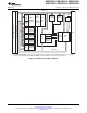
3.6.2 Watchdog Block
The watchdog block on the 2833x/2823x device is similar to the one used on the 240x and 281x devices.
The watchdog module generates an output pulse, 512 oscillator clocks wide (OSCCLK), whenever the 8-
bit watchdog up counter has reached its maximum value. To prevent this, the user disables the counter or
the software must periodically write a 0x55 + 0xAA sequence into the watchdog key register which will
reset the watchdog counter. Figure 3-13 shows the various functional blocks within the watchdog module.
A. The WDRST signal is driven low for 512 OSCCLK cycles.
Figure 3-13. Watchdog Module
The WDINT signal enables the watchdog to be used as a wakeup from IDLE/STANDBY mode.
In STANDBY mode, all peripherals are turned off on the device. The only peripheral that remains
functional is the watchdog. The WATCHDOG module will run off OSCCLK. The WDINT signal is fed to the
LPM block so that it can wake the device from STANDBY (if enabled). See Section 3.7, Low-Power
Modes Block, for more details.
In IDLE mode, the WDINT signal can generate an interrupt to the CPU, via the PIE, to take the CPU out of
IDLE mode.
In HALT mode, this feature cannot be used because the oscillator (and PLL) are turned off and hence so
is the WATCHDOG.
62 Functional Overview Copyright © 2007–2012, Texas Instruments Incorporated
Submit Documentation Feedback
Product Folder Link(s): TMS320F28335 TMS320F28334 TMS320F28332 TMS320F28235 TMS320F28234
TMS320F28232