
Datasheet


TMS320F28335, TMS320F28334, TMS320F28332
TMS320F28235, TMS320F28234, TMS320F28232
SPRS439M –JUNE 2007–REVISED AUGUST 2012
www.ti.com
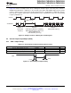
6.10.3 High-Resolution PWM Timing
Table 6-23 shows the high-resolution PWM switching characteristics.
Table 6-23. High-Resolution PWM Characteristics at SYSCLKOUT = (60–150 MHz)
MIN TYP MAX UNIT
Micro Edge Positioning (MEP) step size
(1)
150 310 ps
(1) Maximum MEP step size is based on worst-case process, maximum temperature and maximum voltage. MEP step size will increase
with low voltage and high temperature and decrease with voltage and cold temperature.
Applications that use the HRPWM feature should use MEP Scale Factor Optimizer (SFO) estimation software functions. See the TI
software libraries for details of using SFO function in end applications. SFO functions help to estimate the number of MEP steps per
SYSCLKOUT period dynamically while the HRPWM is in operation.
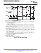
6.10.4 Enhanced Capture (eCAP) Timing
Table 6-24 shows the eCAP timing requirement and Table 6-25 shows the eCAP switching characteristics.
Table 6-24. Enhanced Capture (eCAP) Timing Requirement
(1)
TEST CONDITIONS MIN MAX UNIT
t
w(CAP)
Capture input pulse width Asynchronous 2t
c(SCO)
cycles
Synchronous 2t
c(SCO)
cycles
With input qualifier 1t
c(SCO)
+ t
w(IQSW)
cycles
(1) For an explanation of the input qualifier parameters, see Table 6-13.
Table 6-25. eCAP Switching Characteristics
PARAMETER TEST CONDITIONS MIN MAX UNIT
t
w(APWM)
Pulse duration, APWMx output high/low 20 ns
140 Electrical Specifications Copyright © 2007–2012, Texas Instruments Incorporated
Submit Documentation Feedback
Product Folder Link(s): TMS320F28335 TMS320F28334 TMS320F28332 TMS320F28235 TMS320F28234
TMS320F28232