
Datasheet


TMS320F2810, TMS320F2811, TMS320F2812
TMS320C2810, TMS320C2811, TMS320C2812
www.ti.com
SPRS174T –APRIL 2001–REVISED MAY 2012
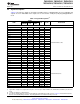
Table 2-2. Signal Descriptions
(1)
(continued)
PIN NO.
NAME I/O/Z
(2)
PU/PD
(3)
DESCRIPTION
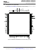
179-BALL 176-PIN 128-PIN
GHH/ZHH PGF PBK
JTAG AND MISCELLANEOUS SIGNALS
Oscillator Input – input to the internal
oscillator. This pin is also used to feed an
external clock. The 28x can be operated with
an external clock source, provided that the
proper voltage levels be driven on the
X1/XCLKIN pin. It should be noted that the
X1/XCLKIN K9 77 58 I – X1/XCLKIN pin is referenced to the 1.8-V (or
1.9-V) core digital power supply (V
DD
), rather
than the 3.3-V I/O supply (V
DDIO
). A clamping
diode may be used to clamp a buffered clock
signal to ensure that the logic-high level does
not exceed V
DD
(1.8 V or 1.9 V) or a 1.8-V
oscillator may be used.
X2 M9 76 57 O – Oscillator Output
Output clock derived from SYSCLKOUT to be
used for external wait-state generation and as
a general-purpose clock source. XCLKOUT is
either the same frequency, 1/2 the frequency,
or 1/4 the frequency of SYSCLKOUT. At reset,
XCLKOUT F11 119 87 O – XCLKOUT = SYSCLKOUT/4. The XCLKOUT
signal can be turned off by setting bit 3
(CLKOFF) of the XINTCNF2 register to 1.
Unlike other GPIO pins, the XCLKOUT pin is
not placed in a high-impedance state during
reset.
Test Pin. Reserved for TI. Must be connected
TESTSEL A13 134 97 I PD
to ground.
Device Reset (in) and Watchdog Reset (out).
Device reset. XRS causes the device to
terminate execution. The PC will point to the
address contained at the location 0x3FFFC0.
When XRS is brought to a high level,
execution begins at the location pointed to by
the PC. This pin is driven low by the DSP
XRS D6 160 113 I/O PU when a watchdog reset occurs. During
watchdog reset, the XRS pin will be driven low
for the watchdog reset duration of
512 XCLKIN cycles.
The output buffer of this pin is an open-drain
with an internal pullup (100 µA, typical). It is
recommended that this pin be driven by an
open-drain device.
Test Pin. Reserved for TI. On F281x devices,
TEST1 must be left unconnected. On C281x
TEST1 M7 67 51 I/O – devices, this pin is a “no connect (NC)”
(that is, this pin is not connected to any
circuitry internal to the device).
Test Pin. Reserved for TI. On F281x devices,
TEST2 must be left unconnected. On C281x
TEST2 N7 66 50 I/O – devices, this pin is a “no connect (NC)”
(that is, this pin is not connected to any
circuitry internal to the device).
Copyright © 2001–2012, Texas Instruments Incorporated Introduction 19
Submit Documentation Feedback
Product Folder Link(s): TMS320F2810 TMS320F2811 TMS320F2812 TMS320C2810 TMS320C2811 TMS320C2812