
Datasheet


TMS320F2810, TMS320F2811, TMS320F2812
TMS320C2810, TMS320C2811, TMS320C2812
SPRS174T –APRIL 2001–REVISED MAY 2012
www.ti.com
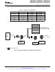
6.23 XINTF Signal Alignment to XCLKOUT
For each XINTF access, the number of lead, active, and trail cycles is based on the internal clock
XTIMCLK. Strobes such as XRD, XWE, and zone chip-select (XZCS) change state in relationship to the
rising edge of XTIMCLK. The external clock, XCLKOUT, can be configured to be either equal to or one-
half the frequency of XTIMCLK.
For the case where XCLKOUT = XTIMCLK, all of the XINTF strobes will change state with respect to the
rising edge of XCLKOUT. For the case where XCLKOUT = one-half XTIMCLK, some strobes will change
state either on the rising edge of XCLKOUT or the falling edge of XCLKOUT. In the XINTF timing tables,
the notation XCOHL is used to indicate that the parameter is with respect to either case; XCLKOUT rising
edge (high) or XCLKOUT falling edge (low). If the parameter is always with respect to the rising edge of
XCLKOUT, the notation XCOH is used.
For the case where XCLKOUT = one-half XTIMCLK, the XCLKOUT edge with which the change will be
aligned can be determined based on the number of XTIMCLK cycles from the start of the access to the
point at which the signal changes. If this number of XTIMCLK cycles is even, the alignment will be with
respect to the rising edge of XCLKOUT. If this number is odd, then the signal will change with respect to
the falling edge of XCLKOUT. Examples include the following:
• Strobes that change at the beginning of an access always align to the rising edge of XCLKOUT. This is
because all XINTF accesses begin with respect to the rising edge of XCLKOUT.
Examples: XZCSL Zone chip-select active-low
XRNWL XR/W active-low
• Strobes that change at the beginning of the active period will align to the rising edge of XCLKOUT if
the total number of lead XTIMCLK cycles for the access is even. If the number of lead XTIMCLK
cycles is odd, then the alignment will be with respect to the falling edge of XCLKOUT.
Examples: XRDL XRD active-low
XWEL XWE active-low
• Strobes that change at the beginning of the trail period will align to the rising edge of XCLKOUT if the
total number of lead + active XTIMCLK cycles (including hardware waitstates) for the access is even. If
the number of lead + active XTIMCLK cycles (including hardware waitstates) is odd, then the alignment
will be with respect to the falling edge of XCLKOUT.
Examples: XRDH XRD inactive-high
XWEH XWE inactive-high
• Strobes that change at the end of the access will align to the rising edge of XCLKOUT if the total
number of lead + active + trail XTIMCLK cycles (including hardware waitstates) is even. If the number
of lead + active + trail XTIMCLK cycles (including hardware waitstates) is odd, then the alignment will
be with respect to the falling edge of XCLKOUT.
Examples: XZCSH Zone chip-select inactive-high
XRNWH XR/W inactive-high
130 Electrical Specifications Copyright © 2001–2012, Texas Instruments Incorporated
Submit Documentation Feedback
Product Folder Link(s): TMS320F2810 TMS320F2811 TMS320F2812 TMS320C2810 TMS320C2811 TMS320C2812