
Datasheet


0
100
200
300
400
500
600
700
0 20 40 60 80 100 120 140 160
SYSCLKOUT (MHz)
Power (mW)
Total Power
0
50
100
150
200
250
0 20 40 60 80 100 120 140 160
SYSCLKOUT (MHz)
Current (mA)
IDD IDDIO
IDD3VFL
IDDA
Total 3.3-V current
TMS320F2810, TMS320F2811, TMS320F2812
TMS320C2810, TMS320C2811, TMS320C2812
www.ti.com
SPRS174T –APRIL 2001–REVISED MAY 2012
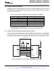
6.5 Current Consumption Graphs
A. Test conditions are as defined in Table 6-1 for operational currents.
B. I
DD
represents the total current drawn from the 1.8-V rail (V
DD
). It includes a small amount of current (<1 mA) drawn
by V
DD1
.
C. I
DDA
represents the current drawn by V
DDA1
and V
DDA2
rails.
D. Total 3.3-V current is the sum of I
DDIO
, I
DD3VFL
, and I
DDA
. It includes a small amount of current (<1 mA) drawn
by V
DDAIO
.
Figure 6-1. F2812/F2811/F2810 Typical Current Consumption Over Frequency
Figure 6-2. F2812/F2811/F2810 Typical Power Consumption Over Frequency
Copyright © 2001–2012, Texas Instruments Incorporated Electrical Specifications 95
Submit Documentation Feedback
Product Folder Link(s): TMS320F2810 TMS320F2811 TMS320F2812 TMS320C2810 TMS320C2811 TMS320C2812