
Datasheet


TMS320F2810, TMS320F2811, TMS320F2812
TMS320C2810, TMS320C2811, TMS320C2812
www.ti.com
SPRS174T –APRIL 2001–REVISED MAY 2012
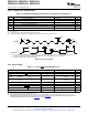
Table 6-14. STANDBY Mode Timing Requirements
MIN NOM MAX UNIT
Without input qualifier 12t
c(CI)
Pulse duration, external wake-up
t
w(WAKE-INT)
cycles
signal
With input qualifier (2 + QUALSTDBY) * t
c(CI)
(1)
(1) QUALSTDBY is a 6-bit field in the LPMCR0 register.
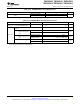
Table 6-15. STANDBY Mode Switching Characteristics
PARAMETER TEST CONDITIONS MIN TYP MAX UNIT
Delay time, IDLE instruction
t
d(IDLE-XCOH)
32t
c(SCO)
45t
c(SCO)
cycles
executed to XCLKOUT high
Delay time, external wake signal to program execution
resume
(1)
Without input qualifier 12t
c(CI)
• Wake-up from Flash
cycles
– Flash module in active
With input qualifier 12t
c(CI)
+ t
w(WAKE-INT)
state
t
d(WAKE-STBY)
Without input qualifier 1125t
c(SCO)
• Wake-up from Flash
cycles
– Flash module in sleep
With input qualifier 1125t
c(SCO)
+ t
w(WAKE-INT)
state
Without input qualifier 12t
c(CI)
• Wake-up from SARAM
cycles
With input qualifier 12t
c(CI)
+ t
w(WAKE-INT)
(1) This is the time taken to begin execution of the instruction that immediately follows the IDLE instruction. Execution of an ISR (triggered
by the wake-up) signal involves additional latency.
Copyright © 2001–2012, Texas Instruments Incorporated Electrical Specifications 109
Submit Documentation Feedback
Product Folder Link(s): TMS320F2810 TMS320F2811 TMS320F2812 TMS320C2810 TMS320C2811 TMS320C2812