
Datasheet


Bit 0 Bit(n-1) (n-2) (n-3) (n-4)
Bit 0 Bit(n-1) (n-2) (n-3) (n-4)
CLKX
FSX
DX
M30
M31
DR
M28
M24
M29
M25
LSB
MSB
M32
M33
TMS320F28069, TMS320F28068, TMS320F28067, TMS320F28066
TMS320F28065, TMS320F28064, TMS320F28063, TMS320F28062
www.ti.com
SPRS698D –NOVEMBER 2010–REVISED DECEMBER 2012
5.14.1.2 McBSP as SPI Master or Slave Timing
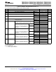
Table 5-38. McBSP as SPI Master or Slave Timing Requirements (CLKSTP = 10b, CLKXP = 0)
MASTER SLAVE
NO. UNIT
MIN MAX MIN MAX
M30 t
su(DRV-CKXL)
Setup time, DR valid before CLKX low 30 8P – 10 ns
M31 t
h(CKXL-DRV)
Hold time, DR valid after CLKX low 1 8P – 10 ns
M32 t
su(BFXL-CKXH)
Setup time, FSX low before CLKX high 8P + 10 ns
M33 t
c(CKX)
Cycle time, CLKX 2P
(1)
16P ns
(1) 2P = 1/CLKG
Table 5-39. McBSP as SPI Master or Slave Switching Characteristics (CLKSTP = 10b, CLKXP = 0)
over recommended operating conditions (unless otherwise noted)
MASTER SLAVE
NO. PARAMETER UNIT
MIN MAX MIN MAX
M24 t
h(CKXL-FXL)
Hold time, FSX low after CLKX low 2P
(1)
ns
M25 t
d(FXL-CKXH)
Delay time, FSX low to CLKX high P ns
M28 t
dis(FXH-DXHZ)
Disable time, DX high impedance following 6 6P + 6 ns
last data bit from FSX high
M29 t
d(FXL-DXV)
Delay time, FSX low to DX valid 6 4P + 6 ns
(1) 2P = 1/CLKG
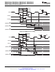
For all SPI slave modes, CLKX must be a minimum of 8 CLKG cycles. Also CLKG should be LSPCLK/2
by setting CLKSM = CLKGDV = 1. With maximum LSPCLK speed of 90 MHz, CLKX maximum frequency
is LSPCLK/16 , that is 5.625 MHz and P = 11.11 ns.
Figure 5-35. McBSP Timing as SPI Master or Slave: CLKSTP = 10b, CLKXP = 0
Copyright © 2010–2012, Texas Instruments Incorporated Peripheral and Electrical Specifications 115
Submit Documentation Feedback
Product Folder Links: TMS320F28069 TMS320F28068 TMS320F28067 TMS320F28066 TMS320F28065
TMS320F28064 TMS320F28063 TMS320F28062