
Datasheet


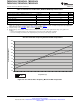


Zero-Pin Oscillator Frequency Movement With Temperature
9.6
9.7
9.8
9.9
10
10.1
10.2
10.3
10.4
10.5
10.6
–40
–30
–20 –10 0 10 20
30
40 50 60 70 80 90 100 110 120
Temperature (°C)
Output Frequency (MHz)
Typical
Max
TMS320F28030, TMS320F28031, TMS320F28032
TMS320F28033, TMS320F28034, TMS320F28035
SPRS584J –APRIL 2009–REVISED OCTOBER 2013
www.ti.com
Table 6-5. Internal Zero-Pin Oscillator (INTOSC1/INTOSC2) Characteristics
PARAMETER MIN TYP MAX UNIT
Internal zero-pin oscillator 1 (INTOSC1) at 30°C
(1)(2)
Frequency 10.000 MHz
Internal zero-pin oscillator 2 (INTOSC2) at 30°C
(1)(2)
Frequency 10.000 MHz
Step size (coarse trim) 55 kHz
Step size (fine trim) 14 kHz
Temperature drift
(3)
3.03 4.85 kHz/°C
Voltage (V
DD
) drift
(3)
175 Hz/mV
(1) In order to achieve better oscillator accuracy (10 MHz ± 1% or better) than shown, refer to the oscillator calibration example in
2803x C/C++ Header Files and Peripheral Examples (literature number SPRC892), and the Oscillator Compensation Guide Application
Report (literature number SPRAB84). Refer to Figure 6-6 for TYP/MAX values.
(2) Frequency range ensured only when VREG is enabled, VREGENZ = V
SS
.
(3) Output frequency of the internal oscillators follows the direction of both the temperature gradient and voltage (V
DD
) gradient. For
example:
• Increase in temperature will cause the output frequency to increase per the temperature coefficient.
• Decrease in voltage (V
DD
) will cause the output frequency to decrease per the voltage coefficient.
Figure 6-6. Zero-Pin Oscillator Frequency Movement With Temperature
114 Electrical Specifications Copyright © 2009–2013, Texas Instruments Incorporated
Submit Documentation Feedback
Product Folder Links: TMS320F28030 TMS320F28031 TMS320F28032 TMS320F28033 TMS320F28034
TMS320F28035