
Datasheet


0.1 Fm
10kW
(typ)
10kW
(typ)
TMP421
DXP
DXN
V+
8
7
6
5
2
1
R
S
(2)
R
S
(2)
C
DIFF
(3)
C
DIFF
(3)
R
S
(2)
R
S
(2)
GND
SCL
SDA
+5V
SMBus
Controller
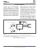
Diode-connectedconfiguration :
(1)
SeriesResistance
Transistor-connectedconfiguration :
(1)
A1
A0
4
3
TMP421
TMP422
TMP423
www.ti.com
SBOS398C –JULY 2007–REVISED MAY 2012
APPLICATION INFORMATION
The TMP421 is a two-channel digital temperature For proper remote temperature sensing operation, the
sensor that combines a local die temperature- TMP421 requires only a transistor connected
measurement channel and a remote-junction between DXP and DXN pins. If the remote channel is
temperature-measurement channel, and is available not utilized, DXP can be left open or tied to GND.
in SOT23-8 and DSBGA-8 packages. The TMP422
The TMP422 requires transistors connected between
(three-channel), and TMP423 (four-channel) are
DX1 and DX2 and between DX3 and DX4. Unused
digital temperature sensors that combine a local die
channels on the TMP422 must be connected to GND.
temperature measurement channel and two or three
The TMP423 requires a transistor connected to each
remote junction temperature measurement channels,
positive channel (DXP1, DXP2, and DXP3), with the
respectively, in a single SOT23-8 package. These
base of each channel tied to the common negative,
devices are two-wire- and SMBus interface-
DXN. For an unused channel, the TMP423 DXP pin
compatible and are specified over a temperature
can be left open or tied to GND.
range of –40°C to +125°C. The TMP421/22/23 each
contain multiple registers for holding configuration
The TMP421/22/23 SCL and SDA interface pins each
information and temperature measurement results.
require pull-up resistors as part of the communication
bus. A 0.1μF power-supply bypass capacitor is
recommended for local bypassing. Figure 11,
Figure 12, and Figure 13 show typical configurations
for the TMP421, TMP422, and TMP423, respectively.
(1) Diode-connected configuration provides better settling time. Transistor-connected configuration provides better series resistance
cancellation.
(2) R
S
(optional) should be < 1.5kΩ in most applications. Selection of R
S
depends on application; see the Filtering section.
(3) C
DIFF
(optional) should be < 1000pF in most applications. Selection of C
DIFF
depends on application; see the Filtering section and
Figure 6, Remote Temperature Error vs Differential Capacitance.
Figure 11. TMP421 Basic Connections
Copyright © 2007–2012, Texas Instruments Incorporated Submit Documentation Feedback 9
Product Folder Link(s): TMP421 TMP422 TMP423