
Datasheet


"#$$
"#$#
SBOS231G − JANUARY 2002 − REVISED NOVEMBER 2007
www.ti.com
9
acknowledges reception of the data byte. The next byte
transmitted by the slave is the least significant byte. The
master acknowledges reception of the data byte. The
master may terminate data transfer by generating a
Not-Acknowledge on reception of any data byte, or
generating a START or STOP condition.
SMBus ALERT FUNCTION
The TMP101 supports the SMBus Alert function. When
the TMP101 is operating in Interrupt Mode (TM = 1), the
ALERT pin of the TMP101 may be connected as an
SMBus Alert signal. When a master senses that an ALERT
condition is present on the ALERT line, the master sends
an SMBus Alert command (00011001) on the bus. If the
ALERT pin of the TMP101 is active, the TMP101 will
acknowledge the SMBus Alert command and respond by
returning its slave address on the SDA line. The eighth bit
(LSB) of the slave address byte will indicate if the
temperature exceeding T
HIGH
or falling below T
LOW
caused the ALERT condition. For POL = 0, this bit will be
LOW if the temperature is greater than or equal to T
HIGH
.
This bit will be HIGH if the temperature is less than T
LOW
.
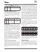
The polarity of this bit will be inverted if POL = 1. Refer to
Figure 8 for details of this sequence.
If multiple devices on the bus respond to the SMBus Alert
command, arbitration during the slave address portion of
the SMBus alert command will determine which device will
clear its ALERT status. If the TMP101 wins the arbitration,
its ALERT pin will become inactive at the completion of the
SMBus Alert command. If the TMP101 loses the
arbitration, its ALERT pin will remain active.
The TMP100 will also respond to the SMBus ALERT
command if its TM bit is set to 1. Since it does not have an
ALERT pin, the master needs to periodically poll the
device by issuing an SMBus Alert command. If the
TMP100 has generated an ALERT, it will acknowledge the
SMBus Alert command and return its slave address in the
next byte.
GENERAL CALL
The TMP100 and TMP101 respond to the I
2
C General Call
address (0000000) if the eighth bit is 0. The device will
acknowledge the General Call address and respond to
commands in the second byte. If the second byte is
00000100, the TMP100 and TMP101 will latch the status
of their address pins, but will not reset. If the second byte
is 00000110, the TMP100 and TMP101 will latch the status
of their address pins and reset their internal registers.
POR (POWER-ON RESET)
The TMP100 and TMP101 both have on-chip power-on
reset circuits that reset the device to default settings when
the device is powered on. This circuit activates when the
power supply is less than 0.3V for more than 100ms. If the
TMP100 and TMP101 are powered down by removing
supply voltage from the device, but the supply voltage is
not assured to be less than 0.3V, it is recommended to
issue a General Call reset command on the I
2
C interface
bus to ensure that the TMP100 and TMP101 are
completely reset.
HIGH-SPEED MODE
In order for the I
2
C bus to operate at frequencies above
400kHz, the master device must issue an Hs-mode master
code (00001XXX) as the first byte after a START condition
to switch the bus to high-speed operation. The TMP100
and TMP101 will not acknowledge this byte as required by
the I
2
C specification, but will switch their input filters on
SDA and SCL and their output filters on SDA to operate in
Hs-mode, allowing transfers at up to 3.4MHz. After the
Hs-mode master code has been issued, the master will
transmit an I
2
C slave address to initiate a data transfer
operation. The bus will continue to operate in Hs-mode
until a STOP condition occurs on the bus. Upon receiving
the STOP condition, the TMP100 and TMP101 will switch
their input and output filters back to fast-mode operation.