
Datasheet


www.ti.com
HPD Pins
DDC Channels
Configuring the TMDS341A as a 2:1 Switch
Layout Considerations
Connecting Cables Longer Than 5 m
TMDS Signal Path
TMDS341A
SLLS702B – MAY 2006 – REVISED MARCH 2007
APPLICATION INFORMATION (continued)
When the power source of the device, V
CC
, is off and the power source to termination, AV
CC
, is on, the output
leakage current (I
o(off)
) specification ensures leakage current is limited to 10-µA or less.
The PRE pin provides 3-dB de-emphasis, allowing output signal pre-conditioning to offset interconnect losses
from the TMDS341A outputs to a TMDS receiver. PRE is recommended to be low to the circuit design of a
stand-alone switch box.
The input of the HPD_SINK is 5-V tolerant, allowing direct connection to 5-V signals. The HPD pin output
resistance is 35- Ω typically. A 1-k Ω 10% resistor is recommended to be connected from an HPD pin at the
TMDS341A to the HPD pin of the HDMI connector.
The DDC channels are designed with a bi-directional pass gate, providing 5-V signal tolerance. The 5-V
tolerance allows direct connection to a standard I
2
C bus. The level shifter between 3.3 V and 5 V I
2
C interface
can be eliminated.
The TMDS341A can be configured as a 2-to-1 switch by pulling the source selector pin (S1, S2, S3) of the
non-active port low and leaving the corresponding TMDS inputs, SCL, SDA, and HPD pins open.
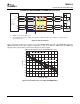
The high-speed TMDS inputs are the most critical paths for the TMDS341A. There are several considerations to
minimize discontinuities on these transmission lines between the connectors and the device:
• Maintain 100- Ω differential transmission line impedance into and out of the TMDS341A
• Keep an uninterrupted ground plane beneath the high-speed I/Os
• Keep the ground-path vias to the device as close as possible to allow the shortest return current path
• Layout of the TMDS differential inputs should be with the shortest stubs from the connectors
When using the TMDS341A with cables longer than 5 m, the impact to the TMDS signal path as well as the
DDC signal path must be considered.
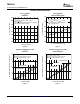
The TMDS341A receiver equalization circuit provides the capability of compensating inter-symbol interference
(ISI) losses in a 5-m 28-AWG DVI cable. Typical cable measurements indicate that the TMDS341A can drive a
5-m 28-AWG HDMI cable and pass the eye mask at the output of a HDMI source (TP1) and a 10-m 28-AWG
HDMI cable and pass the eye mask at the input of a HDMI sink (TP2). Figure 36 through Figure 39 show the
eye mask measurement results.
Figure 36. Eye Diagram at Output 5-m 28-AWG Cable vs Figure 37. Eye Diagram Recovered by TMDS341A vs TP1
TP1 Eye Mask Eye Mask
20
Submit Documentation Feedback