
Datasheet


TLV5614
2.7-V TO 5.5-V 12-BIT 3-µS QUADRUPLE DIGITAL-TO-ANALOG CONVERTERS
WITH POWER DOWN
SLAS188B – SEPTEMBER 1998 – REVISED APRIL 2003
22
POST OFFICE BOX 655303 • DALLAS, TEXAS 75265
APPLICATION INFORMATION
;–––––––––––––––––––––––––––––––––––––––––––––––––––––––––––––––––––––––––––––––
; Processor: 80C51
;
; Description:
;
; This program generates a differential in-phase
(sine) on (OUTA–OUTB) ; and it’s quadrature (cosine)
as a differential signal on (OUTC–OUTD).
;
; 1998, Texas Instruments Inc.
;–––––––––––––––––––––––––––––––––––––––––––––––––––––––––––––––––––––––––––––––
NAME GENIQ
MAIN SEGMENT CODE
ISR SEGMENT CODE
SINTBL SEGMENT CODE
VAR1 SEGMENT DATA
STACK SEGMENT IDATA
;–––––––––––––––––––––––––––––––––––––––––––––––––––––––––––––––––––––––––––––––
; Code start at address 0, jump to start
;–––––––––––––––––––––––––––––––––––––––––––––––––––––––––––––––––––––––––––––––
CSEG AT 0
LJMP start ; Execution starts at address 0 on power–up.
;–––––––––––––––––––––––––––––––––––––––––––––––––––––––––––––––––––––––––––––––
; Code in the timer0 interrupt vector
;–––––––––––––––––––––––––––––––––––––––––––––––––––––––––––––––––––––––––––––––
CSEG AT 0BH
LJMP timer0isr ; Jump vector for timer 0 interrupt is 000Bh
;–––––––––––––––––––––––––––––––––––––––––––––––––––––––––––––––––––––––––––––––
; Global variables need space allocated
;–––––––––––––––––––––––––––––––––––––––––––––––––––––––––––––––––––––––––––––––
RSEG VAR1
temp_ptr: DS 1
rolling_ptr: DS 1
;–––––––––––––––––––––––––––––––––––––––––––––––––––––––––––––––––––––––––––––––;
Interrupt service routine for timer 0 interrupts
;–––––––––––––––––––––––––––––––––––––––––––––––––––––––––––––––––––––––––––––––
RSEG ISR
timer0isr:
PUSH PSW
PUSH ACC
CLR INT1 ; pulse LDAC low
SETB INT1 ; to latch all 4 previous values at the same time
; 1st thing done in timer isr => fixed period
CLR T0 ; set CS low
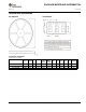
; The signal to be output on each DAC is a sine function.
; One cycle of a sine wave is held in a table @ sinevals
; as 32 samples of msb, lsb pairs (64 bytes).
; We have ; one pointer which rolls round this table, rolling_ptr,
; incrementing by 2 bytes (1 sample) on each interrupt (at the end of
; this routine).
; The DAC samples are read at an offset to this rolling pointer:
; DAC Function Offset from rolling_ptr
; A sine 0
; B inverse sine 32
; C cosine 16
; D inverse cosine48
MOV DPTR,#sinevals; set DPTR to the start of the table
; of sine signal values
MOV R7,rolling_ptr; R7 holds the pointer
;into the sine table
MOV A,R7 ; get DAC A msb
MOVC A,@A+DPTR ; msb of DAC A is in the ACC