
Datasheet


ka ka
V
z z
I
R1
1
R2
D
D
+¢ = » ´
æ ö
ç ÷
è ø
KA
K
ka
V
z
I
D
D
=
( )
REF( dev )
6
REF A
REF
A
V
10
V T 25 C
ppm
V
C T
´
= °
a =
° D
æ ö
ç ÷
æ ö
è ø
ç ÷
è ø
REF
KA
V
V
D
D
(3) The dynamic impedance is defined as
TLV431, TLV431A, TLV431B
SLVS139U –JULY 1996–REVISED JANUARY 2014
www.ti.com
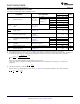
Electrical Characteristics for TLV431
at 25°C free-air temperature (unless otherwise noted)
TLV431
PARAMETER TEST CONDITIONS UNIT
MIN TYP MAX
T
A
= 25°C 1.222 1.24 1.258
TLV431C 1.21 1.27
V
KA
= V
REF
,
V
REF
Reference voltage V
T
A
= full range
(1)
I
K
= 10 mA
TLV431I 1.202 1.278
(see Figure 1)
TLV431Q 1.194 1.286
TLV431C 4 12
V
KA
= V
REF
, I
K
= 10 mA
(1)
V
REF
deviation over full temperature
V
REF(dev)
TLV431I 6 20 mV
range
(2)
(see Figure 1)
TLV431Q 11 31
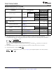
Ratio of V
REF
change in cathode V
KA
= V
REF
to 6 V, I
K
= 10 mA
–1.5 –2.7 mV/V
voltage change (see Figure 2)
I
K
= 10 mA, R1 = 10 kΩ,
R2 = open
I
ref
Reference terminal current 0.15 0.5 µA
(see Figure 2)
TLV431C 0.05 0.3
I
K
= 10 mA, R1 = 10 kΩ,
I
ref
deviation over full temperature
I
ref(dev)
R2 = open
(1)
TLV431I 0.1 0.4 µA
range
(2)
(see Figure 2)
TLV431Q 0.15 0.5
TLV431C/I 55 80
Minimum cathode current for
I
K(min)
V
KA
= V
REF
(see Figure 1) µA
regulation
TLV431Q 55 100
I
K(off)
Off-state cathode current V
REF
= 0, V
KA
= 6 V (see Figure 3) 0.001 0.1 µA
V
KA
= V
REF
, f ≤ 1 kHz, I
K
= 0.1 mA to 15 mA
|z
KA
| Dynamic impedance
(3)
0.25 0.4 Ω
(see Figure 1)
(1) Full temperature ranges are –40°C to 125 ° C for TLV431Q, –40°C to 85°C for TLV431I, and 0°C to 70°C for TLV431C.
(2) The deviation parameters V
REF(dev)
and I
ref(dev)
are defined as the differences between the maximum and minimum values obtained over
the rated temperature range. The average full-range temperature coefficient of the reference input voltage, αV
REF
, is defined as:
where ΔT
A
is the rated operating free-air temperature range of the device.
αV
REF
can be positive or negative, depending on whether minimum V
REF
or maximum V
REF
, respectively, occurs at the lower
temperature.
spacer
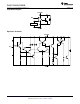
When the device is operating with two external resistors (see Figure 2), the total dynamic impedance of the circuit is defined as:
4 Submit Documentation Feedback Copyright © 1996–2014, Texas Instruments Incorporated
Product Folder Links :TLV431 TLV431A TLV431B