
Datasheet


"#$%&'
"#$%&(
SBOS321D − MARCH 2005 − REVISED JULY 2005
www.ti.com
8
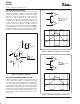
RELAXATION OSCILLATOR
The TLV350x can easily be configured as a simple and
inexpensive relaxation oscillator. In Figure 4, the R2
network sets the trip threshold at 1/3 and 2/3 of the supply.
Since this is a high-speed circuit, the resistor values are
rather low in order to minimize the effect of parasitic
capacitance. The positive input alternates between 1/3 of
V+ and 2/3 of V+ depending on whether the output is low
or high. The time to charge (or discharge) is 0.69R
1
C.
Therefore, the period is 1.38R
1
C. For 62pF and 1kΩ as
shown in Figure 4, the output is calculated to be 10.9MHz.
An implementation of this circuit oscillated at 9.6MHz.
Parasitic capacitance and component tolerances explain
the difference between theory and actual performance.
V+
f=10MHz
V
S
=5V
2/3 (V+)
1/3 (V+)
R
1
1k
Ω
R
2
5k
Ω
R
2
5k
Ω
R
2
5k
Ω
V
OUT
V
C
V+
t
C
62pF
1.38R
1
C
t
Figure 4. Relaxation Oscillator
HIGH-SPEED WINDOW COMPARATOR
A window comparator circuit is used to determine when a
signal is between two voltages. The TLV3502 can readily
be used to create a high-speed window comparator. V
HI
is the upper voltage threshold, and V
LO
is the lower voltage
threshold. When V
IN
is between these two thresholds, the
output in Figure 5 is high. Figure 6 shows a simple means
of obtaining an active low output. Note that the reference
levels are connected differently between Figure 5 and
Figure 6. The operating voltage range of either circuit is
2.7V to 5.5V.
TLV3502b
TLV3502a
V
OUT
V
HI
V
LO
V
IN
SN74LVC1G02
V
HI
V
LO
V
IN
V
OUT
V
Time
Figure 5. Window Comparator—Active High
TLV3502b
TLV3502a
V
OUT
V
HI
V
LO
V
IN
SN74AHC00
V
HI
V
LO
V
IN
V
OUT
V
Time
Figure 6. Window Comparator—Active Low