
Datasheet


TLV320AIC3110
SLAS647B –DECEMBER 2009–REVISED MAY 2012
www.ti.com
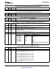
Page 1 / Register 35 (0x23): DAC_L and DAC_R Output Mixer Routing
READ/ RESET
BIT DESCRIPTION
WRITE VALUE
D7–D6 R/W 00 00: DAC_L is not routed anywhere.
01: DAC_L is routed to the left-channel mixer amplifier.
10: DAC_L is routed directly to the HPL driver.
11: Reserved
D5 R/W 0 0: MIC1LP input is not routed to the left-channel mixer amplifier.
1: MIC1LP input is routed to the left-channel mixer amplifier.
D4 0 0: MIC1RP input is not routed to the left-channel mixer amplifier.
1: MIC1RP input is routed to the left-channel mixer amplifier.
D3–D2 R/W 00 00: DAC_R is not routed anywhere.
01: DAC_R is routed to the right-channel mixer amplifier.
10: DAC_R is routed directly to the HPR driver.
11: Reserved
D1 R/W 0 0: MIC1RP input is not routed to the right-channel mixer amplifier.
1: MIC1RP input is routed to the right-channel mixer amplifier.
D0 R/W 0 0: HPL driver output is not routed to the HPR driver.
1: HPL driver output is routed to the HPR driver input (used for differential output mode).
Page 1 / Register 36 (0x24): Left Analog Vol to HPL
READ/ RESET
BIT DESCRIPTION
WRITE VALUE
D7 R/W 0 0: Left-channel analog volume to left-channel headphone output driver is muted if bits D6–D0 are also
111 1111.
1: Left-channel analog volume control is routed to HPL output driver.
D6–D0 R/W 111 1111 Left-channel analog volume control gain (non-linear) for the HPL output driver, 0 dB to –78 dB. See
Table 5-38.
Page 1 / Register 37 (0x25): Right Analog Vol to HPR
READ/ RESET
BIT DESCRIPTION
WRITE VALUE
D7 R/W 0 0: Right-channel analog volume to right-channel headphone output driver is muted if bits D6–D0 are
also 111 1111.
1: Right-channel analog volume control is routed to HPR output driver.
D6–D0 R/W 111 1111 Right-channel analog volume control gain (non-linear) for the HPR output driver, 0 dB to –78 dB. See
Table 5-38.
Page 1 / Register 38 (0x26): Left Analog Vol to SPL
READ/ RESET
BIT DESCRIPTION
WRITE VALUE
D7 R/W 0 0: Left-channel analog volume to left-channel class-D output driver is muted if bits D6–D0 are also 111
1111.
1: Left-channel analog volume control output is routed to left-channel class-D output driver.
D6–D0 R/W 111 1111 Left-channel analog volume control output gain (non-linear) for the left-channel class-D output driver,
0 dB to –78 dB. See Table 5-38.
Page 1 / Register 39 (0x27): Right Analog Vol to SPR
READ/ RESET
BIT DESCRIPTION
WRITE VALUE
D7 R/W 0 0: Right-channel analog volume to right-channel class-D output driver is muted if bits D6–D0 are also
111 1111.
1: Right-channel analog volume control output is routed to right-channel class-D output driver.
D6–D0 R/W 111 1111 Right-channel analog volume control output gain (non-linear) for the right-channel class-D output driver,
0 dB to –78 dB. See Table 5-38.
104 REGISTER MAP Copyright © 2009–2012, Texas Instruments Incorporated
Submit Documentation Feedback
Product Folder Links: TLV320AIC3110