
Datasheet


www.ti.com
111D110
111
X
1DIN (Read)
DIN (Write)
Don’t care
D15
D15 D13D14
D13D14
0D9D10D11DOUT (Read) D15 D13D14 D12
Data to be Written Into Register
D7 - D0
D7 - D0
D7 - D0
R/W Broadcast
Register
Address
Register
Address
SMARTDM Device
Address
Register Content
Master FS
DIN
Master Slave2 Slave1 Slave0 Master Slave2 Slave1 Slave0 Master Slave2 Slave1 Slave0Slave0
Write
Command
Reg Addr (D15-D13)
R/W (D12)
Broadcast (D11)
D10-D8
001
0
1
111
010
0
1
111
100
0
1
111
110
0
1
111
Data Frame Control Frame
Time Slot
AIC20 #1 AIC20 #2 AIC20 #1 AIC20 #2
Data Frame
Host Port Interface
TLV320AIC20, TLV320AIC21
TLV320AIC24, TLV320AIC25
TLV320AIC20K, TLV320AIC24K
SLAS363D – MARCH 2002 – REVISED APRIL 2005
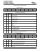
Figure 29. Control Frame Data Format
A. NOTE: In this example, the broadcast operation (D11 = 1) is used to program the four control registers of Reg.1,
Reg.2, Reg.4, and Reg.6 in all four DSP codecs of two TLV320AIC2xs in cascade (Master, Slave2, Slave1, and
Slave0) during the same frame (i.e., register 1 of the four codecs contains the same data).
The host port uses a 2-wire serial interface (SCL, SDA) to program channel six of each of the codec control
registers, and selectable protocol between S
2
C mode and I
2
C mode. The S
2
C is a write-only mode, and the I
2
C
is a read-write mode selected by bits D1-D0 (HPC bits) of control register 2. If the host interface is not needed,
the two pins of SCL and SDA can be programmed to become general-purpose I/Os. If selected to be used as I/O
pins, the SDA and SCL pins become output and input pins respectively, determined by D1 and D0.
Both S
2
C and I
2
C require a SMARTDM device address to communicate with the AIC2x. One of SMARTDM's
advanced features is the automatic cascade detection (ACD) that enables SMARTDM to automatically detect the
total number of codecs in the serial connection and use this information to assign each codec a distinct
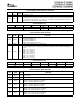
SMARTDM device address. Table 2 lists device addresses assigned to each codec in the cascade by the
SMARTDM. The master always has the highest position in the cascade. For example in Figure 20 , there is a
total of 4 codecs in the cascade (i.e., one master and 3 slaves), then the device addresses in row 4 are used in
which the master is codec 1 with a device address of 0000.
34