
Datasheet


www.ti.com
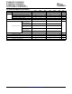
Digital Inputs and Outputs
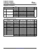
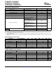
ADC Path Filter
TLV320AIC12, TLV320AIC13
TLV320AIC14, TLV320AIC15
TLV320AIC12K, TLV320AIC14K
SLWS115E – OCTOBER 2001 – REVISED JANUARY 2007
F
s
= 8 kHz, Outputs Not Loaded
PARAMETER
(1)
MIN TYP MAX UNIT
V
OH
High-level output voltage, DOUT 0.8 IOVDD V
V
OL
Low-level output voltage, DOUT 0.1 IOVDD V
I
IH
High-level input current, any digital input 0.5 µA
I
IL
Low-level input current, any digital input 0.5 µA
C
I
Input capacitance 3 pF
C
o
Output capacitance 5 pF
(1) For V
IH
(Input high level), when IOVDD < 1.6 V, minimum V
IH
is 1.1V.
Fs = 8 KHz
(1) (2)
TEST
PARAMETER MIN TYP MAX MIN TYP MAX UNIT
CONDITIONS
FIR FILTER IIR FILTER
0 Hz to 30 Hz -0.5 0.2 -0.5 0.2
300 Hz to 3 Hz -0.5 0.25 -0.5 0.25
3.3 Hz -0.5 0.3 -1.5 0.3
Filter gain relative to gain
dB
at 1020 Hz
3.6 KHz -3 -3
4 kHz -35 -20
≥ 4.4 KHz -74 -60
(1) The filter gain outside of the passband is measured with respect to the gain at 1020 Hz. The analog input test signal is a sine wave with
0 dB = 4 V
I(PP)
as the reference level for the analog input signal. The pass band is 0 to 3600 Hz for an 8-KHz sample rate. This pass
band scales linearly with the sample rate.
(2) The filter characteristics are specified by design and are not tested in production.
7
Submit Documentation Feedback