
Datasheet


SLOS220J − JULY 1998 − REVISED FEBRUARY 2004
11
WWW.TI.COM
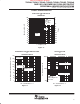
TYPICAL CHARACTERISTICS
Table of Graphs
FIGURE
V
IO
Input offset voltage vs Common-mode input voltage 1, 2
I
IB
Input bias current vs Free-air temperature 3, 4
I
IO
Input offset current vs Free-air temperature 3, 4
V
OH
High-level output voltage vs High-level output current 5, 6
V
OL
Low-level output voltage vs Low-level output current 7, 8
V
O(PP)
Peak-to-peak output voltage vs Frequency 9, 10
Open-loop gain vs Frequency 11, 12
Phase vs Frequency 11, 12
A
VD
Differential voltage amplification vs Load resistance 13
Capacitive load vs Load resistance 14
Z
o
Output impedance vs Frequency 15, 16
CMRR Common-mode rejection ratio vs Frequency 17
k
SVR
Supply-voltage rejection ratio vs Frequency 18, 19
I
DD
Supply current
vs Supply voltage 20
I
DD
Supply current
vs Free-air temperature
21
Amplifier turnon characteristics 22
Amplifier turnoff characteristics 23
Supply current turnon 24
Supply current turnoff 25
Shutdown supply current vs Free-air temperature 26
SR Slew rate vs Supply voltage 27
V
n
Equivalent input noise voltage
vs Frequency 28, 29
V
n
Equivalent input noise voltage
vs Common-mode input voltage 30, 31
THD Total harmonic distortion vs Frequency 32, 33
THD+N Total harmonic distortion plus noise vs Peak-to-peak signal amplitude 34, 35
vs Frequency 11, 12
φ
m
Phase margin
vs Load capacitance
36
φ
m
Phase margin
vs Free-air temperature 37
Gain bandwidth product
vs Supply voltage 38
Gain bandwidth product
vs Free-air temperature
39
Large signal follower 40, 41
Small signal follower 42, 43
Inverting large signal 44, 45
Inverting small signal 46, 47
Device TLV2465A is Obsolete