
Datasheet


SLOS186C − FEBRUARY 1997 − REVISED AUGUST 2006
5
POST OFFICE BOX 655303 • DALLAS, TEXAS 75265
absolute maximum ratings over operating free-air temperature range (unless otherwise noted)
†
Supply voltage, V
DD
(see Note 1) 16 V. . . . . . . . . . . . . . . . . . . . . . . . . . . . . . . . . . . . . . . . . . . . . . . . . . . . . . . . . . . .
Differential input voltage, V
ID
(see Note 2) ±V
DD
. . . . . . . . . . . . . . . . . . . . . . . . . . . . . . . . . . . . . . . . . . . . . . . . . . .
Input voltage range, V
I
(any input, see Note 1) V
DD−
−0.3 V to V
DD+
. . . . . . . . . . . . . . . . . . . . . . . . . . . . . . . . . .
Input current, I
I
(each input) ±5 mA. . . . . . . . . . . . . . . . . . . . . . . . . . . . . . . . . . . . . . . . . . . . . . . . . . . . . . . . . . . . . . .
Output current, I
O
±50 mA. . . . . . . . . . . . . . . . . . . . . . . . . . . . . . . . . . . . . . . . . . . . . . . . . . . . . . . . . . . . . . . . . . . . . . .
Total current into V
DD+
±50 mA. . . . . . . . . . . . . . . . . . . . . . . . . . . . . . . . . . . . . . . . . . . . . . . . . . . . . . . . . . . . . . . . . .
Total current out of V
DD−
±50 mA. . . . . . . . . . . . . . . . . . . . . . . . . . . . . . . . . . . . . . . . . . . . . . . . . . . . . . . . . . . . . . . .
Duration of short-circuit current (at or below) 25°C (see Note 3) unlimited. . . . . . . . . . . . . . . . . . . . . . . . . . . . . .
Continuous total power dissipation See Dissipation Rating Table. . . . . . . . . . . . . . . . . . . . . . . . . . . . . . . . . . . . .
Operating free-air temperature range, T
A
: I suffix −40°C to 125°C. . . . . . . . . . . . . . . . . . . . . . . . . . . . . . . . . . . .
Q suffix −40°C to 125°C. . . . . . . . . . . . . . . . . . . . . . . . . . . . . . . . . . .
M suffix −55°C to 125°C. . . . . . . . . . . . . . . . . . . . . . . . . . . . . . . . . .
Storage temperature range, T
stg
−65°C to 150°C. . . . . . . . . . . . . . . . . . . . . . . . . . . . . . . . . . . . . . . . . . . . . . . . . . .
†
Stresses beyond those listed under “absolute maximum ratings” may cause permanent damage to the device. These are stress ratings only, and
functional operation of the device at these or any other conditions beyond those indicated under “recommended operating conditions” is not
implied. Exposure to absolute-maximum-rated conditions for extended periods may affect device reliability.
NOTES: 1. All voltage values, except differential voltages, are with respect to V
DD −
.
2. Differential voltages are at the noninverting input with respect to the inverting input. Excessive current flows when input is brought
below V
DD−
− 0.3 V.
3. The output may be shorted to either supply. Temperature and/or supply voltages must be limited to ensure that the maximum
dissipation rating is not exceeded.
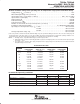
DISSIPATION RATING TABLE
PACKAGE
T
A
≤
25
°
C
DERATING FACTOR
T
A
= 85
°
C
T
A
= 125
°
C
PACKAGE
T
A
≤ 25 C
POWER RATING
DERATING FACTOR
ABOVE T
A
= 25°C
T
A
= 85 C
POWER RATING
T
A
= 125 C
POWER RATING
D−8 725 mW 5.8 mW/°C 377 mW 145 mW
D−14 950 mW 7.6 mW/°C 494 mW 190 mW
FK 1375 mW 11.0 mW/°C 715 mW 275 mW
J 1375 mW 11.0 mW/°C 715 mW 275 mW
JG 1050 mW 8.4 mW/°C — 210 mW
N 1150 mW 9.2 mW/°C 598 mW —
P 1000 mW 8.0 mW/°C 520 mW 200 mW
PW−8 525 mW 4.2 mW/°C 273 mW 105 mW
PW−14 700 mW 5.6 mW/°C 364 mW —
U 700 mW 5.5 mW/°C — 150 mW
W 700 mW 5.5 mW/°C 370 mW 150 mW
recommended operating conditions
I SUFFIX Q SUFFIX M SUFFIX
UNIT
MIN MAX MIN MAX MIN MAX
UNIT
Supply voltage, V
DD±
2.7 8 2.7 8 2.7 8 V
Input voltage range, V
I
V
DD−
V
DD+
−1.3 V
DD−
V
DD+
−1.3 V
DD−
V
DD+
−1.3 V
Common-mode input voltage, V
IC
V
DD−
V
DD+
−1.3 V
DD−
V
DD+
−1.3 V
DD−
V
DD+
−1.3 V
Operating free-air temperature, T
A
−40 125 −40 125 −55 125 °C
NOTE 1: All voltage values, except differential voltages, are with respect to V
DD −
.