
Datasheet


TLC5620C, TLC5620I
QUADRUPLE 8-BIT DIGITAL-TO-ANALOG CONVERTERS
SLAS081E – NOVEMBER 1994 – REVISED NOVEMBER 2001
4
POST OFFICE BOX 655303 • DALLAS, TEXAS 75265
RNG
CLK
DATA
LOAD
LDAC
DAC Update
A1 A0 D7 D6 D5 D4 D3 D2 D1 D0
t
su(DATA-CLK)
t
v(DATA-CLK)
t
w(LDAC)
t
su(LOAD-LDAC)
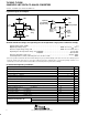
Figure 2. LDAC-Controlled Update
A1 A0 RNG D7 D6 D5 D4 D3 D2 D1 D0
CLK
DATA
LOAD
LDAC
CLK Low
Figure 3. Load-Controlled Update Using 8-Bit Serial Word (LDAC = Low)
A1 A0 RNG D7 D6 D5 D4 D3 D2 D1 D0
CLK
DATA
LOAD
LDAC
CLK Low
Figure 4. LDAC-Controlled Update Using 8-Bit Serial Word
Table 2 lists the A1 and A0 bits and the selection of the updated DACs. The RNG bit controls the DAC output
range. When RNG = low, the output range is between the applied reference voltage and GND, and when
RNG = high, the range is between twice the applied reference voltage and GND.
Table 2. Serial Input Decode
A1 A0 DAC UPDATED
0 0 DACA
0 1 DACB
1 0 DACC
1 1 DACD