
Datasheet


±
SLAS262C − OCTOBER 2000 − REVISED MAY 2003
22
WWW.TI.COM
detailed description (continued)
Table 2. Configuration Register (CFR) Bit Definition
SDI BIT DEFINITION
D11 Always 1. Otherwise the performance is degraded.
D10 Conversion output code format select:
0: BOB (bipolar offset binary);
1: BTC (binary 2s complement)
D9
Sample period select for normal sampling. Don’t care in extended sampling.
D9
0: Long sampling (4x) 44 SCLKs; 1: Short sampling 12 SCLKs
D8 Conversion clock source select:
0: Conversion clock = Internal OSC;
1: Conversion clock = SCLK/4
D7
Input mode select:
0: Single-ended;
1: Pseudodifferential. Pin configuration shown below.
Pin Configuration of TLC3578 and TLC2578 Pin Configuration of TLC3574 and TLC2574
Pin No. Single-ended Pseudodifferential polarity Pin No. Single-ended Pseudodifferential polarity
9
10
A0
A1
Plus
Minus
Pair A 9
10
A0
A1
PLUS
MINUS
Pair A
11
12
A2
A3
Plus
Minus
Pair B 11
12
A2
A3
PLUS
MINUS
Pair B
13
14
A4
A5
Plus
Minus
Pair C
15
16
A6
A7
Plus
Minus
Pair D
D[6:5] Conversion mode select
00: One shot mode
01: Repeat mode
10: Sweep mode
11: Repeat sweep mode.
D[4:3]
Sweep auto sequence select (Note: These bits only take effect in conversion mode 10 and 11.)
D[4:3]
TLC3578 and TLC2578 TLC3574 and TLC2574
Single-ended (by ch) Pseudodifferential (by pair) Single-ended (by ch) Pseudodifferential (by pair)
00: 0−1−2−3−4−5−6−7
01: 0−2−4−6−0−2−4−6
10: 0−0−2−2−4−4−6−6
11: 0−2−0−2−0−2−0−2
00: N/A
01: A−B−C−D−A−B−C−D
10: A−A−B−B−C−C−D−D
11: A−B−A−B−A−B−A−B
00: 0−1−2−3−0−1−2−3
01: 0−2−0−2−0−2−0−2
10: 0−0−1−1−2−2−3−3
11: 0−0−0−0−2−2−2−2
00: N/A
01: A−B−A−B−A−B−A−B
10: N/A
11: A−A−A−A−B−B−B−B
D2 EOC/INT pin function select
0: Pin used as INT
1: Pin used as EOC ( for mode 00 only)
D[1:0] FIFO trigger level (sweep sequence length). Don’t care in one shot mode.
00: Full (INT
generated after FIFO Level 7 filled)
01: 3/4 (INT
generated after FIFO Level 5 filled)
10: 1/2 (INT
generated after FIFO Level 3 filled)
11: 1/4 (INT
generated after FIFO Level 1 filled)
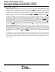
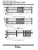
sampling period
The sampling period follows the command period. The selected signal is sampled during this time. The device
has three different sampling modes: normal short mode, normal long mode, and extended mode.
Normal Short Sampling Mode: Sampling time is controlled by the SCLK and lasts 12 SCLK periods. At the
end of sampling, the converter automatically starts the conversion period. After the configuration, the normal
sampling starts automatically after the falling edge of fourth SCLK that follows the falling edge of CS
if CS
triggers the operation, or follows the rising edge of FS if FS initiates the operation, except the FIFO READ and
WRITE CFR commands.