
Datasheet


TLC225x, TLC225xA
Advanced LinCMOS RAIL-TO-RAIL
VERY LOW-POWER OPERATIONAL AMPLIFIERS
SLOS176D – FEBRUARY 1997 – REVISED MARCH 2001
47
POST OFFICE BOX 655303 • DALLAS, TEXAS 75265
APPLICATION INFORMATION
macromodel information
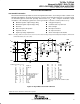
Macromodel information provided was derived using MicroSim Parts, the model generation software used
with MicroSim PSpice. The Boyle macromodel (see Note 5) and subcircuit in Figure 61 are generated using
the TLC225x typical electrical and operating characteristics at T
A
= 25°C. Using this information, output
simulations of the following key parameters can be generated to a tolerance of 20% (in most cases):
Maximum positive output voltage swing
Maximum negative output voltage swing
Slew rate
Quiescent power dissipation
Input bias current
Open-loop voltage amplification
Unity-gain frequency
Common-mode rejection ratio
Phase margin
DC output resistance
AC output resistance
Short-circuit output current limit
NOTE 5: G. R. Boyle, B. M. Cohn, D. O. Pederson, and J. E. Solomon, “Macromodeling of Integrated Circuit Operational Amplifiers”, IEEE Journal
of Solid-State Circuits, SC-9, 353 (1974).
OUT
+
–
+
–
+
–
+
–
+
–
+
–
+
–
+
–
+–
.SUBCKT TLC225x 1 2 3 4 5
C1 11 12 6.369E–12
C2 6 7 25.00E–12
DC 5 53 DX
DE 54 5 DX
DLP 90 91 DX
DLN 92 90 DX
DP 43DX
EGND 99 0 POLY (2) (3,0) (4,0) 0 .5 .5
FB 7 99 POLY (5) VB VC VE VLP
+ VLN 0 57.62E6 –60E6 60E6 60E6 –60E6
GA 6 0 11 12 26.86E–6
GCM 0 6 10 99 2.686E–9
ISS 3 10 DC 3.1E–6
HLIM 90 0 VLIM 1K
J1 11 2 10 JX
J2 12 1 10 JX
R2 6 9 100.0E3
RD1 60 11 37.23E3
RD2 60 12 37.23E3
R01 8 5 84
R02 7 99 84
RP 3 4 71.43E3
RSS 10 99 64.52E6
VAD 60 4 –.5
VB 9 0 DC 0
VC 3 53 DC .605
VE 54 4 DC .605
VLIM 7 8 DC 0
VLP 91 0 DC –.235
VLN 0 92 DC 7.5
.MODEL DX D (IS=800.0E–18)
.MODEL JX PJF (IS=500.0E–15 BETA=139E–6
+ VTO=–.05)
.ENDS
V
CC+
RP
IN –
2
IN+
1
V
CC–
VAD
RD1
11
J1 J2
10
RSS ISS
3
12
RD2
60
VE
54
DE
DP
VC
DC
4
C1
53
R2
6
9
EGND
VB
FB
C2
GCM
GA
VLIM
8
5
RO1
RO2
HLIM
90
DLP
91
DLN
92
VLNVLP
99
7
Figure 61. Boyle Macromodel and Subcircuit
PSpice and Parts are trademarks of MicroSim Corporation.