
Datasheet


TLC04/MF4A-50, TLC14/MF4A-100
BUTTERWORTH FOURTH-ORDER LOW-PASS
SWITCHED-CAPACITOR FILTERS
SLAS021A – NOVEMBER 1986 – REVISED MARCH 1995
9
POST OFFICE BOX 655303 • DALLAS, TEXAS 75265
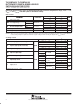
APPLICATION INFORMATION
5 VOC
FILTER IN
(see Note B)
10 kΩ
0.1 µF
10 kΩ
See Note A
–5 V
0 V
TTL
CLKR
OUT
CMOS
CLKIN
0 V
10 V
10 V
4
V
CC–
6 AGND
8 FILTER IN
FILTER
5
φ2φ1
Butterworth
Fourth-Order
Low-Pass Filter
Nonoverlapping
Clock Generator
2 CLKR
1 CLKIN
3LS
V
CC+
7
Level Shift
See Note C
NOTES: A. The external clock used must be of CMOS level because the clock is input to a CMOS Schmitt trigger.
B. The filter input signal should be dc-biased to midsupply or ac-coupled to the terminal.
C. AGND must be biased to midsupply.
Figure 6. External-Clock-Driven Single-Supply Operation