
Datasheet


TL16CP754C, TL16C754C
www.ti.com
SLLS644G –DECEMBER 2007– REVISED MAY 2011
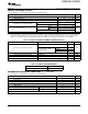
Table 2. Register Reset Functions
(1)
RESET
REGISTER RESET STATE
CONTROL
Interrupt enable register RESET All bits cleared
Interrupt identification register RESET Bit 0 is set. All other bits cleared.
FIFO control register RESET All bits cleared
Line control register RESET Reset to 00011101 (1D hex).
Bit 6–0 cleared. Bit 7 reflects the inverse of the
Modem control register RESET
CLKSEL pin value.
Line status register RESET Bits 5 and 6 set. All other bits cleared.
Modem status register RESET Bits 0–3 cleared. Bits 4–7 input signals.
Bit 6–0 is cleared. Bit 7 reflects the inverse of the
Enhanced feature register RESET
CLKSEL pin value.
Receiver holding register RESET Pointer logic cleared
Transmitter holding register RESET Pointer logic cleared
Transmission control register RESET All bits cleared
Trigger level register RESET All bits cleared
Alternate function register RESET All bits (except AFR4) cleared; AFR4 set
(1) Registers DLL, DLH, SPR, Xon1, Xon2, Xoff1, Xoff2 are not reset by the top-level reset signal RESET,
i.e., they hold their initialization values during reset.
Table 3 summarizes the state of outputs after reset.
Table 3. Signal Reset Functions
SIGNAL RESET CONTROL RESET STATE
TX RESET High
RTS RESET High
DTR RESET High
RXRDY RESET High
TXRDY RESET Low
Interrupts
The '754C UART has interrupt generation and prioritization (six prioritized levels of interrupts) capability. The
interrupt enable register (IER) enables each of the six types of interrupts and the INT signal in response to an
interrupt generation. The IER also can disable the interrupt system by clearing bits 0−3, 5−7. When an interrupt
is generated, the interrupt identification register(IIR) indicates that an interrupt is pending and provides the type
of interrupt through IIR[5−0]. Table 4 summarizes the interrupt control functions.
Copyright © 2007–2011, Texas Instruments Incorporated 11